Description
Introduction
Xodus Amp is one of my oldest projects and has served its many duties proudly and without a fuss. Now its time for a re-visit and upgrade to realize the original dream of the project.
A sad state of affairs
Like many projects, Xodus Amp was designed as a service appliance. Over the years it has been rode hard and put up wet, leaving many scratches and unfinished plates/bezels. The LCD was removed long ago and placed in a computer I used as a headless device, since Xodus Amp no longer served as my desktop computer speaker amp the hole was left unpopulated.
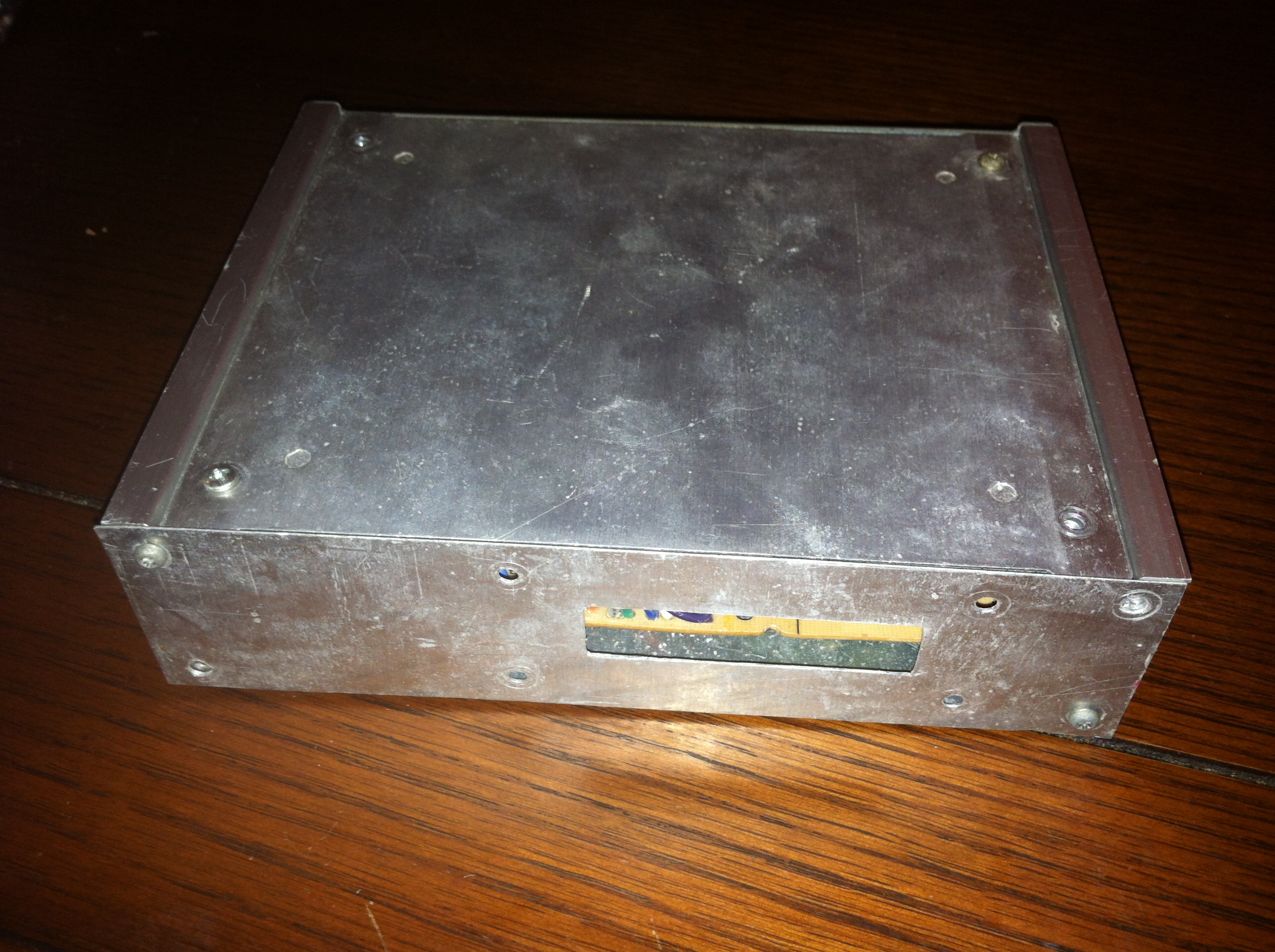
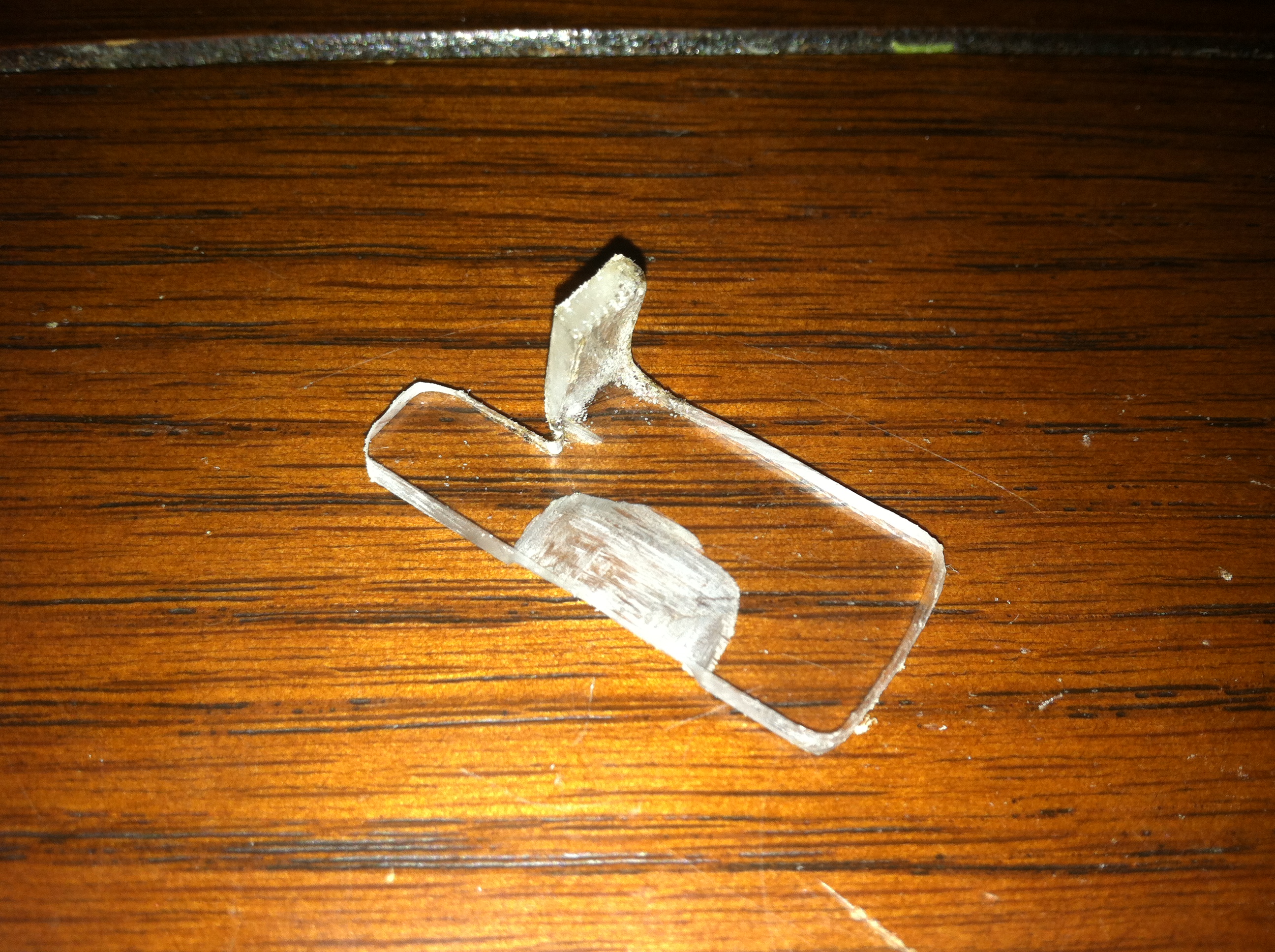
The plexiglass plate that had been cut for the top has cracked years ago so the original metal plate was put back on. These plates are have one issue, they are not perfect rectangles, in the front and back of the unit there is a gap.


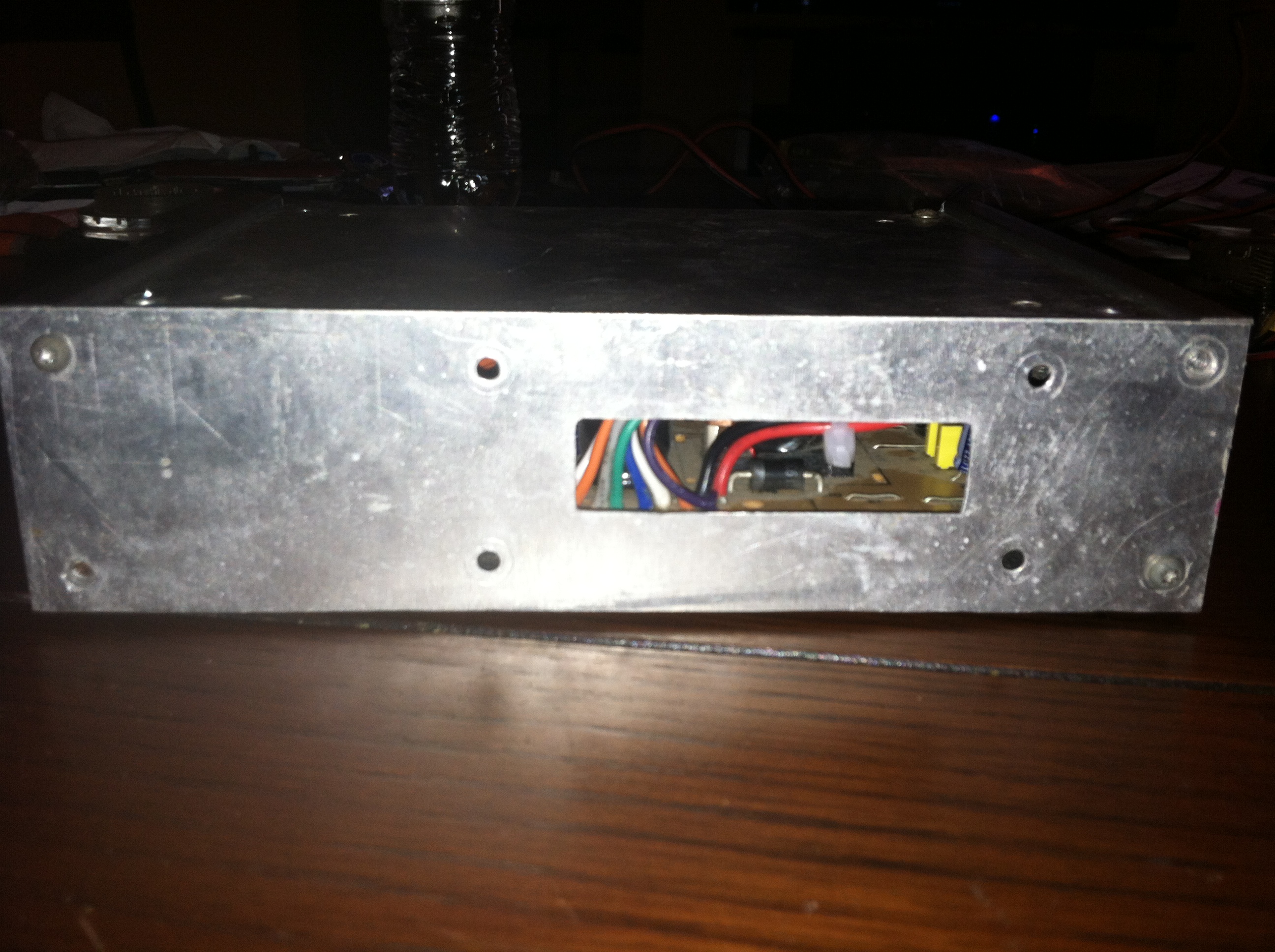
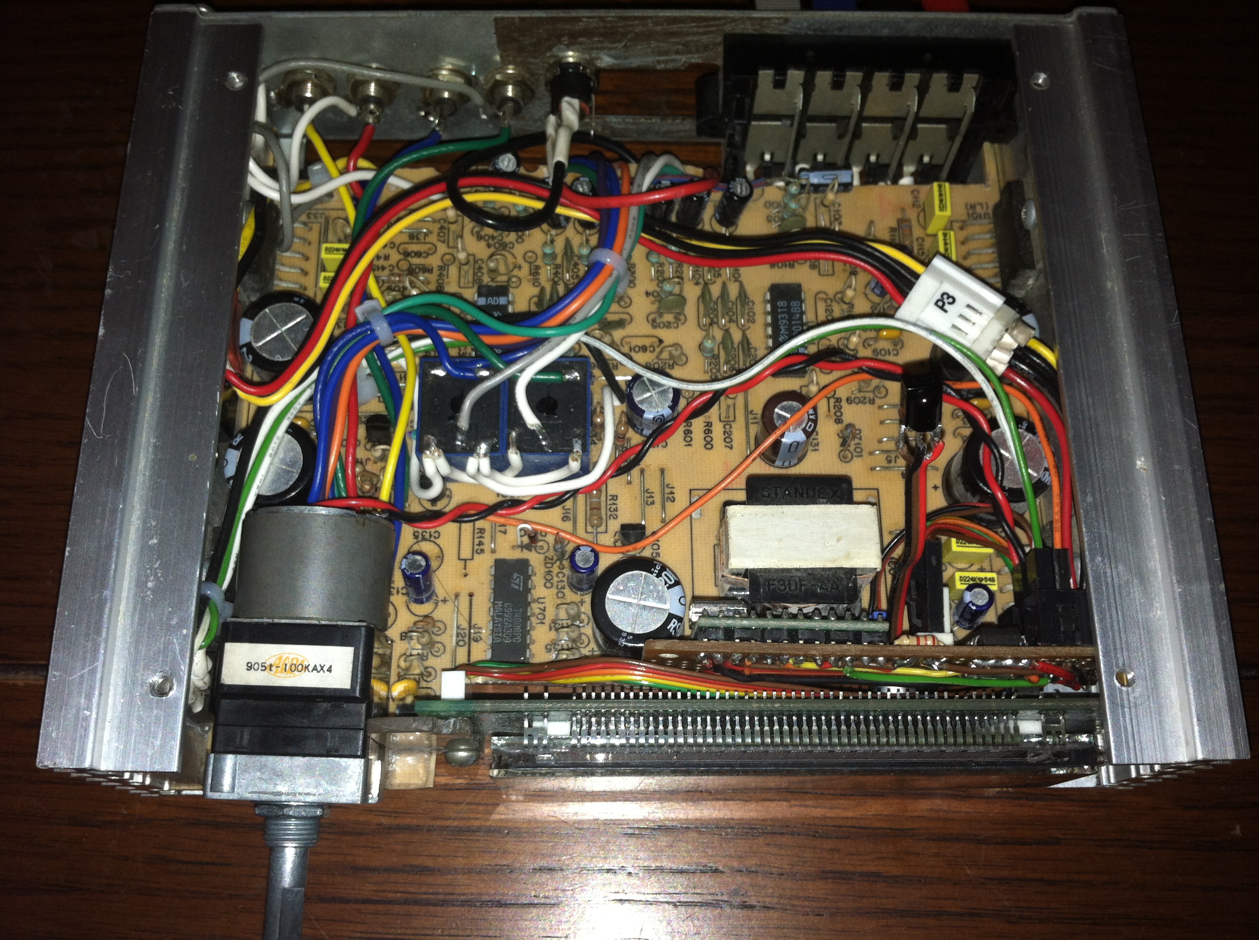
The rear of Xodus Amp has remain unchanged since the very first iteration of this project, its original to the unit and still has the large hole where the input connector used to live. The inside of the unit looks better than the rest of the project in my opinion at this stage. The cutout for the original LCD can also be seen here.
Motorized Potentiometer
One big issue with Xodus Amp from the beginning has always been the lack of a volume control. The amp was designed to be placed in a remote location with the head unit managing the input volume level.
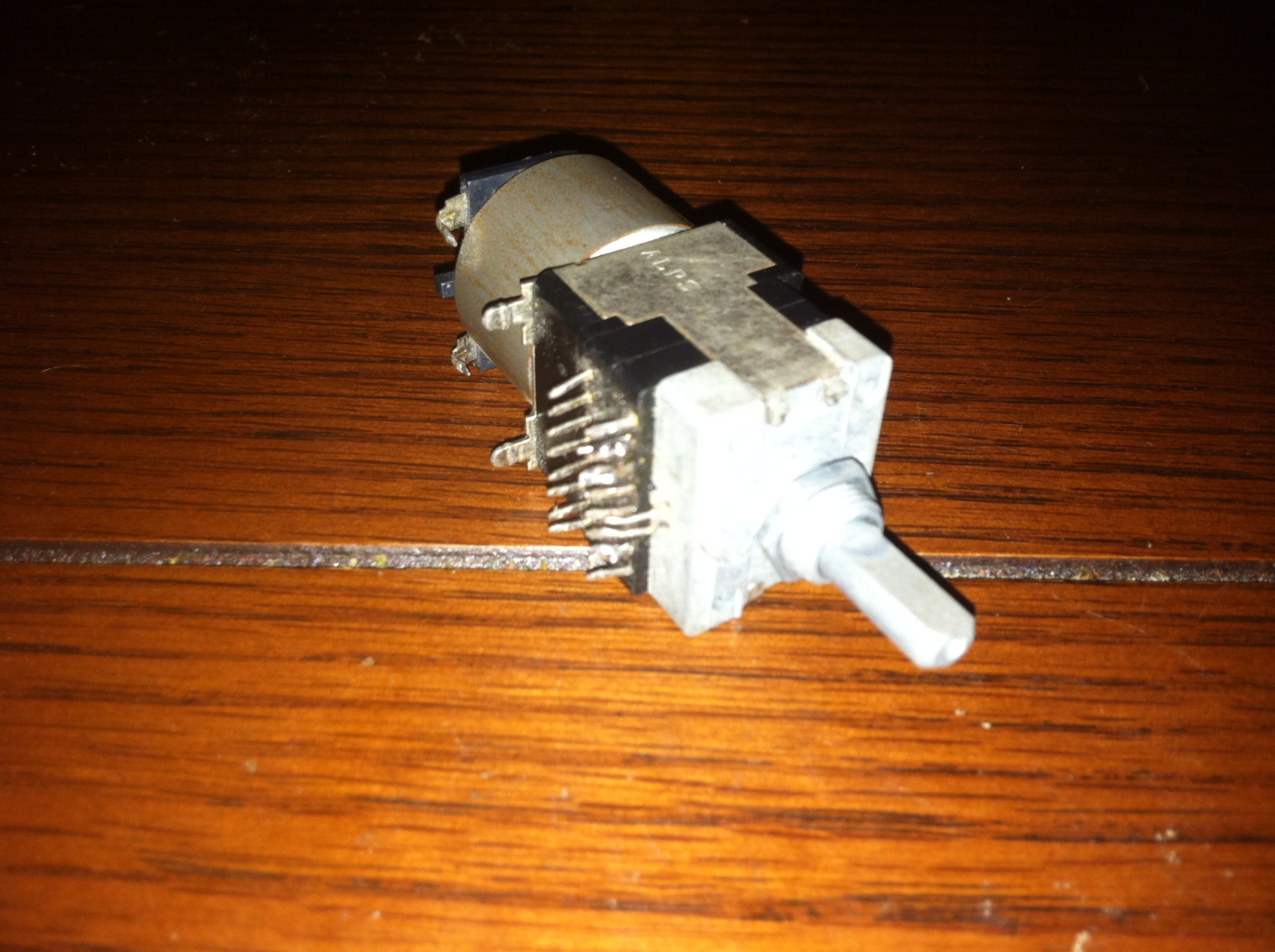
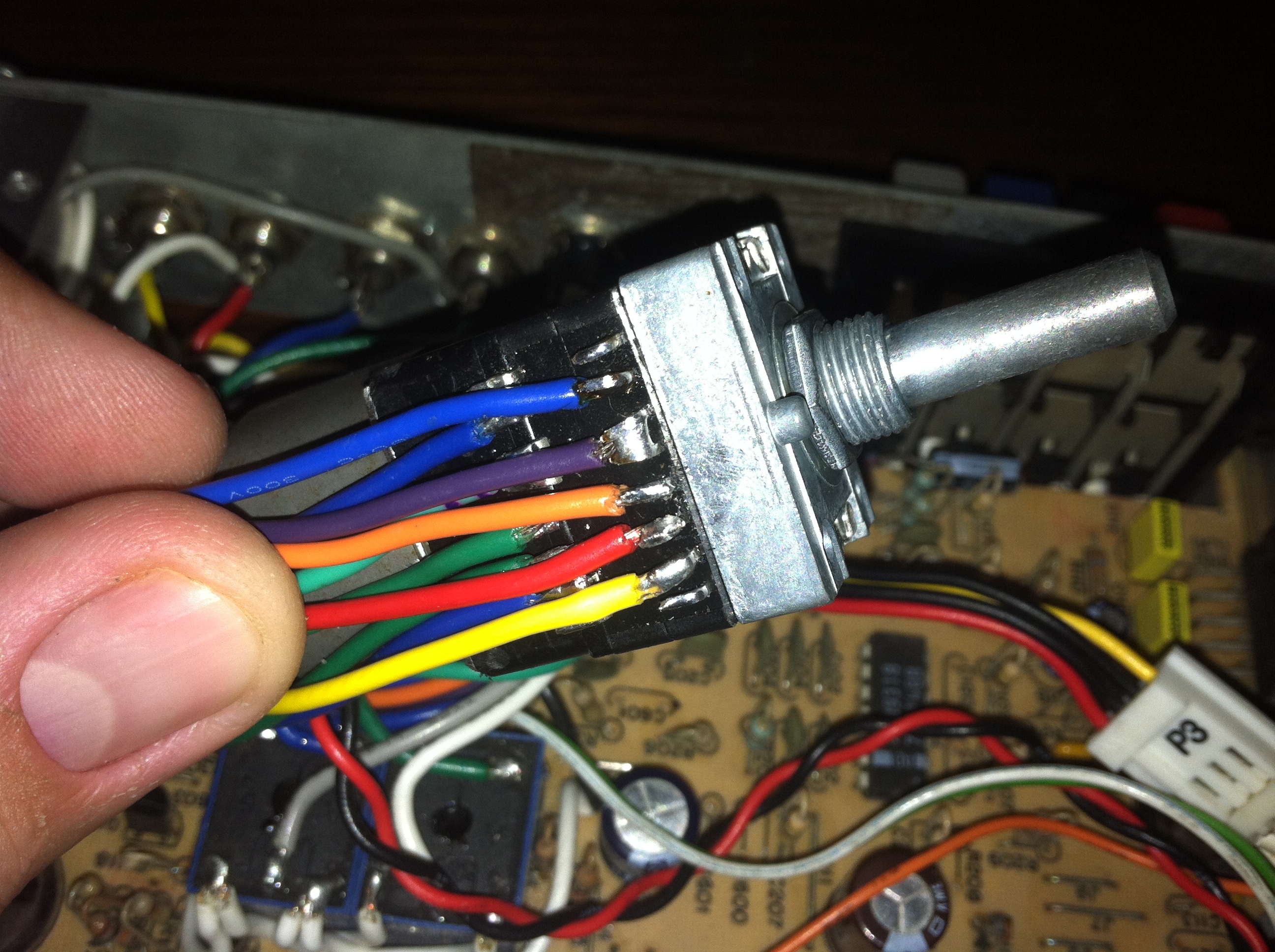
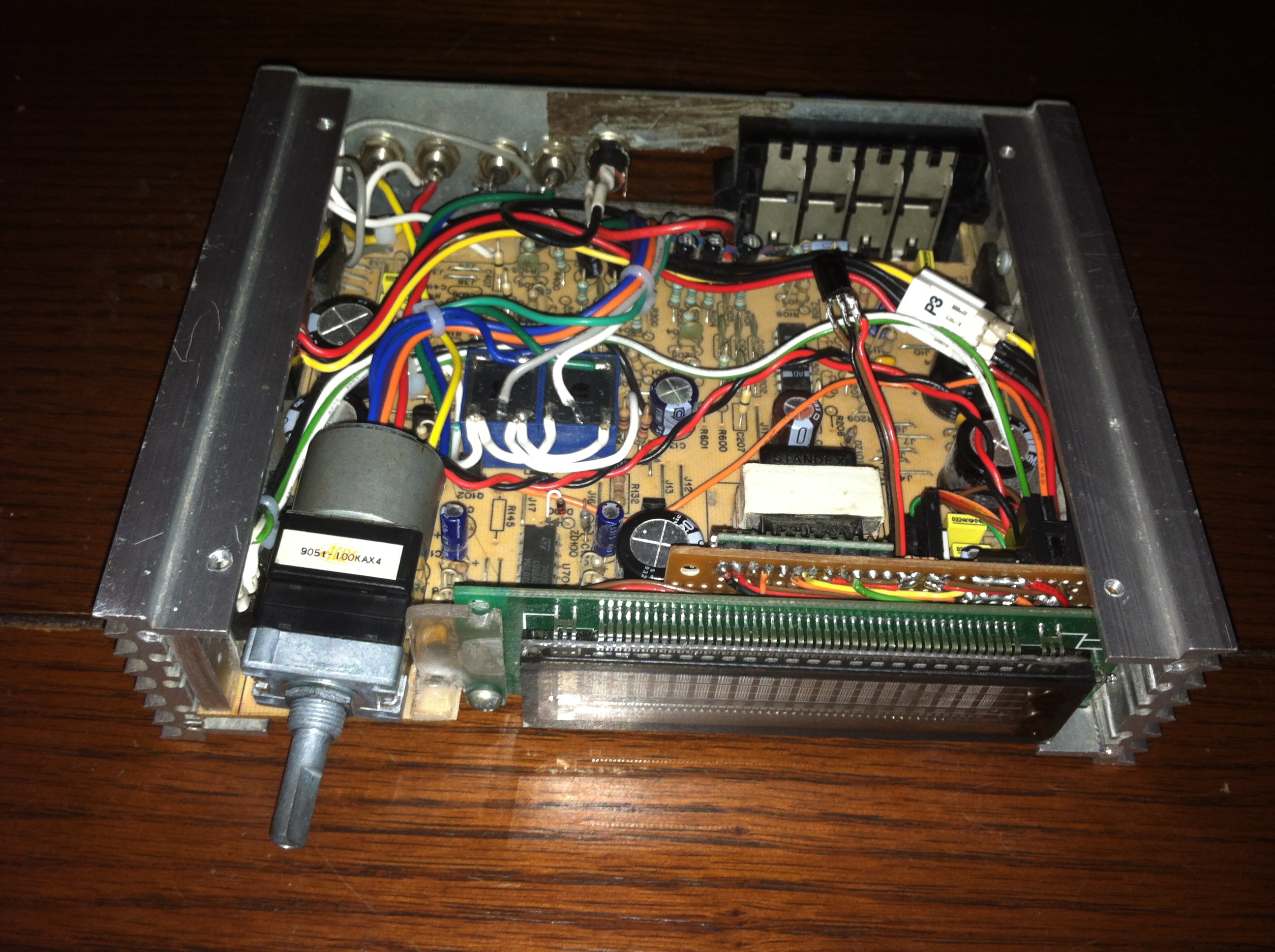
After digging in my parts bin I found this gem, a motorized 4 channel potentiometer manufactured by ALPS. This was desoldered from a piece of stereo equipment many years and has been lying in wait for the day this project would come to be.
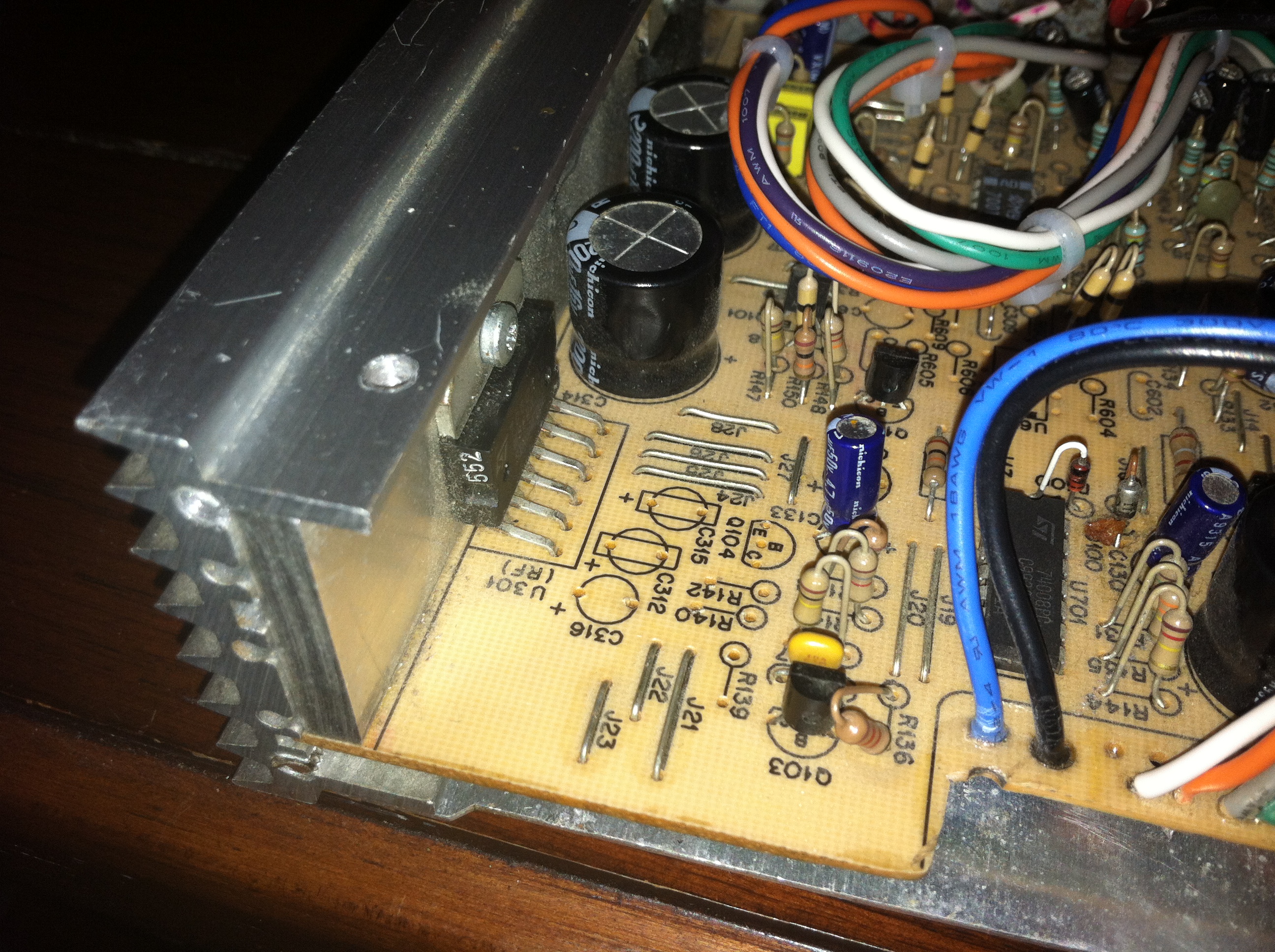
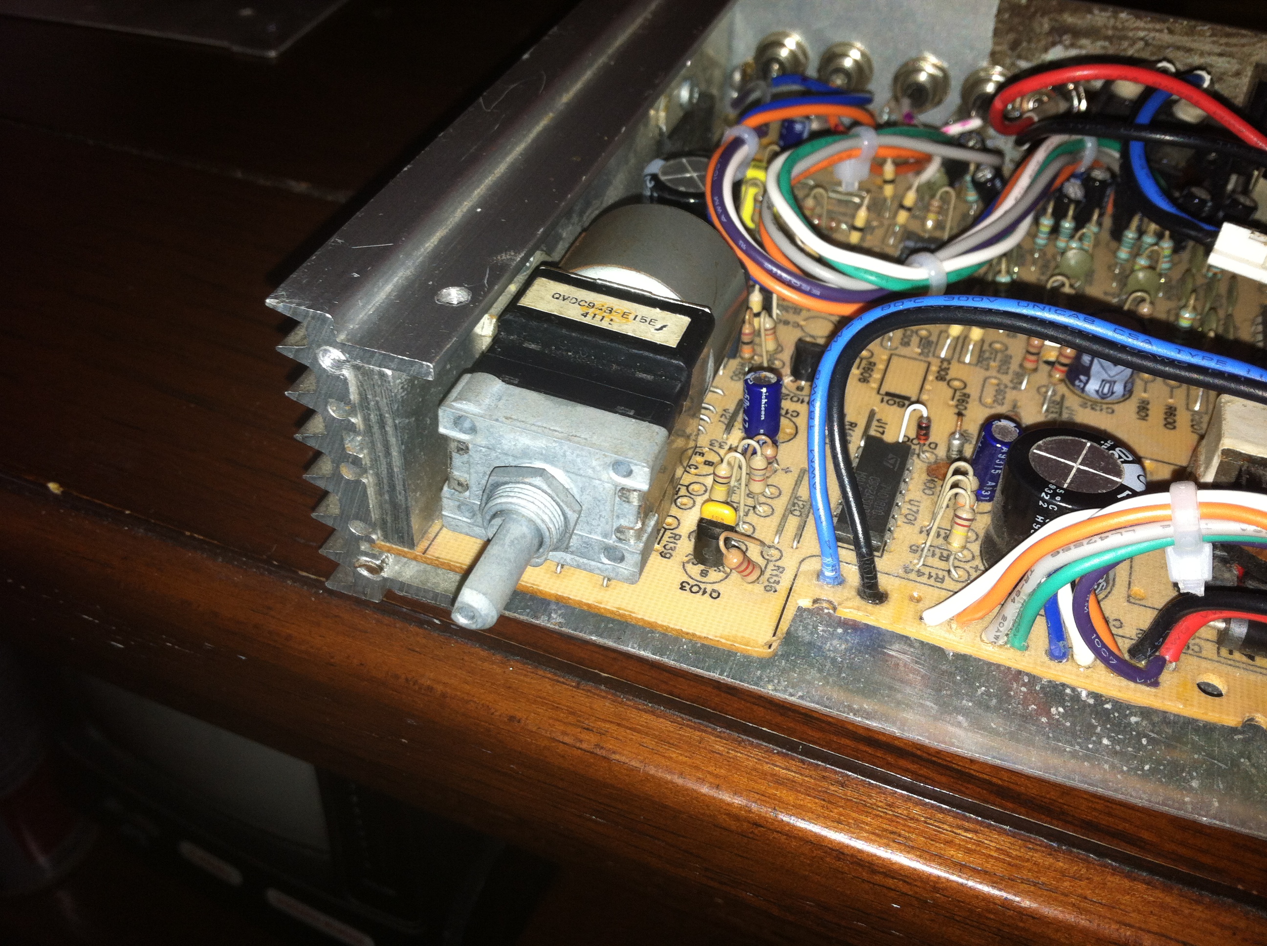
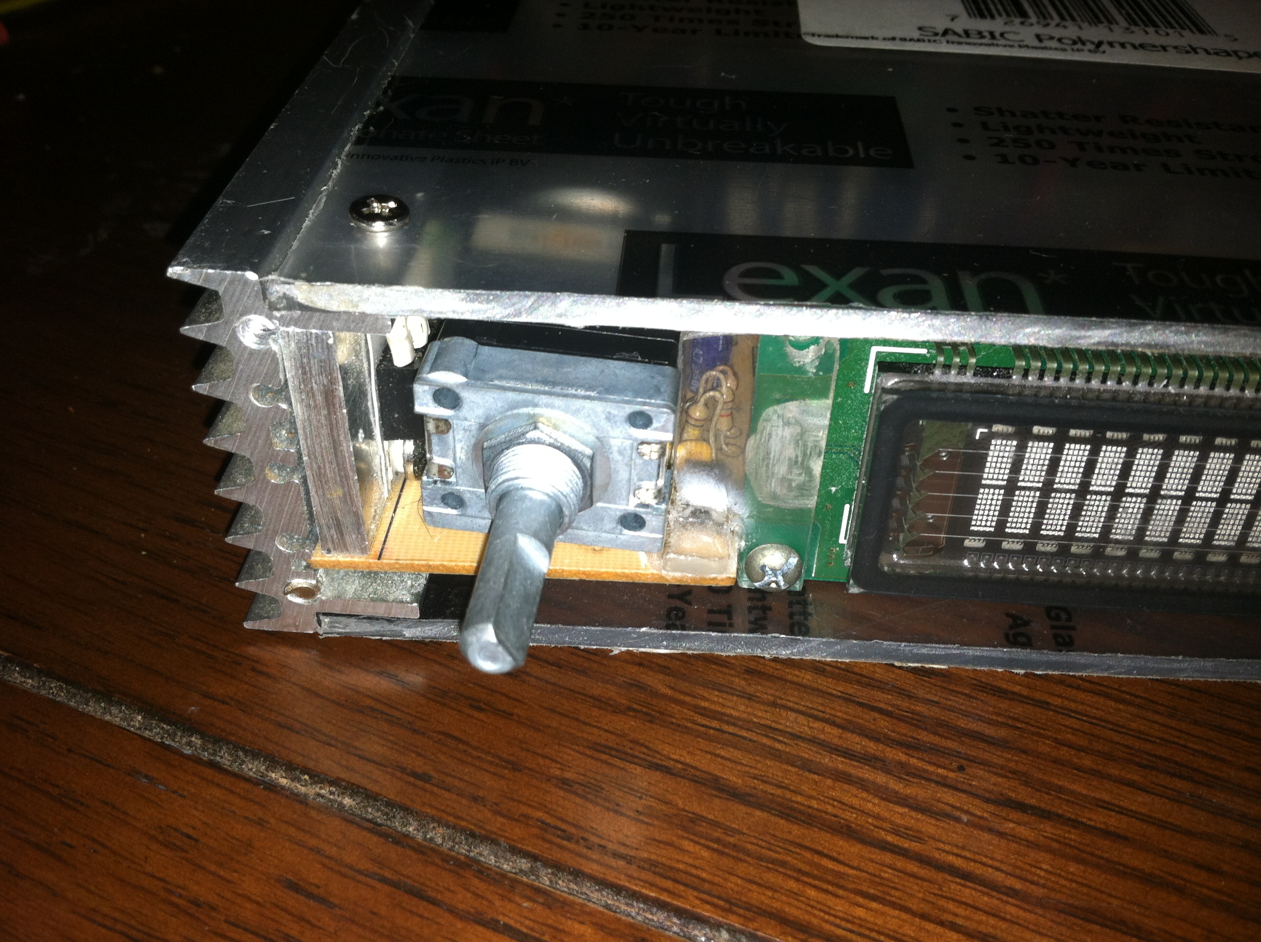
The first order of business was to find a suitable location for the potentiometer, since it had to go in front next to the VFD there was really only one choice. Luckily the location I picked out had a fairly low component count and meant by relocating the components populated in that area the potentiometer could then be mounted. Here you can see underneath the board where the components were relocated. Thankfully there is enough room between the bottom of the PCB and the bottom plate to accommodate the capacitors and the like.
Cutting Lexan
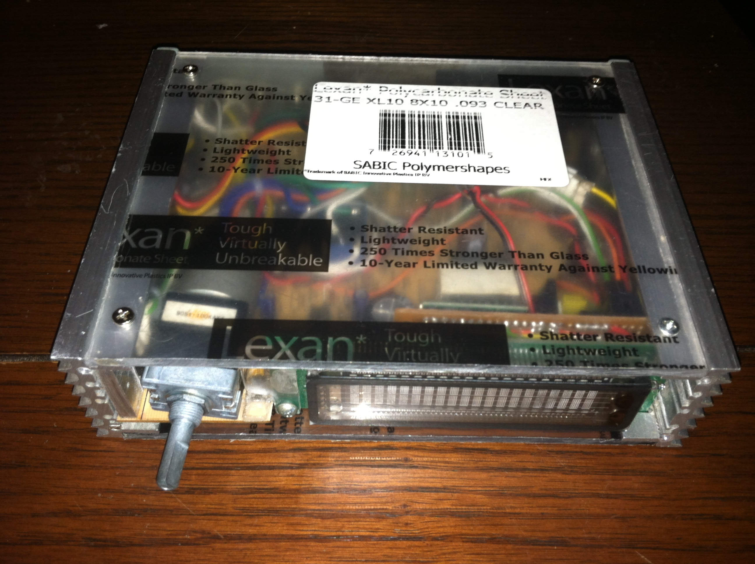
The original top plate cracked years ago, to be fair it was made from the backing of a busted LCD panel. This go around I will be using Lexan which is shatterproof and virtually unbreakable. It is also much easier to work with than traditional plexiglass making it a breeze to cut and not worry about the edges cracking.
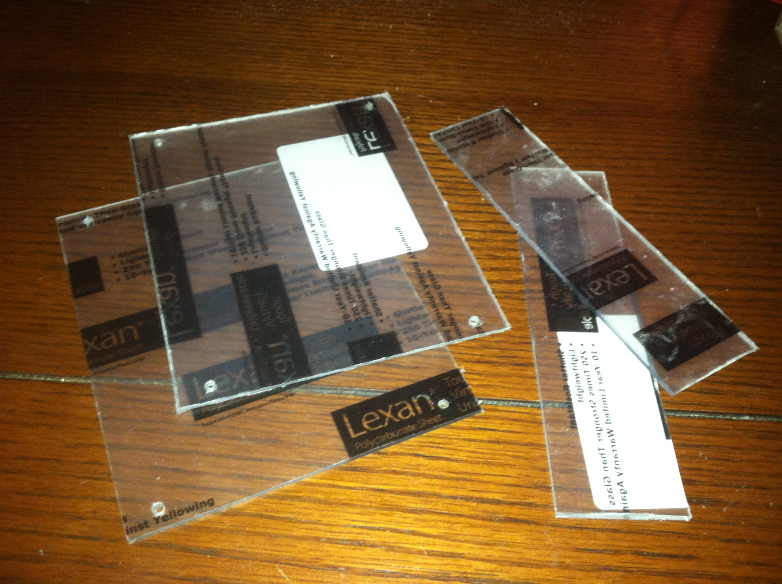

The top/bottom plates and front/back plates were cut and rough sanded/filed to allow the top/bottom plates to fit snugly. The front/back plates were cut but have not been sanded/filed at this stage.
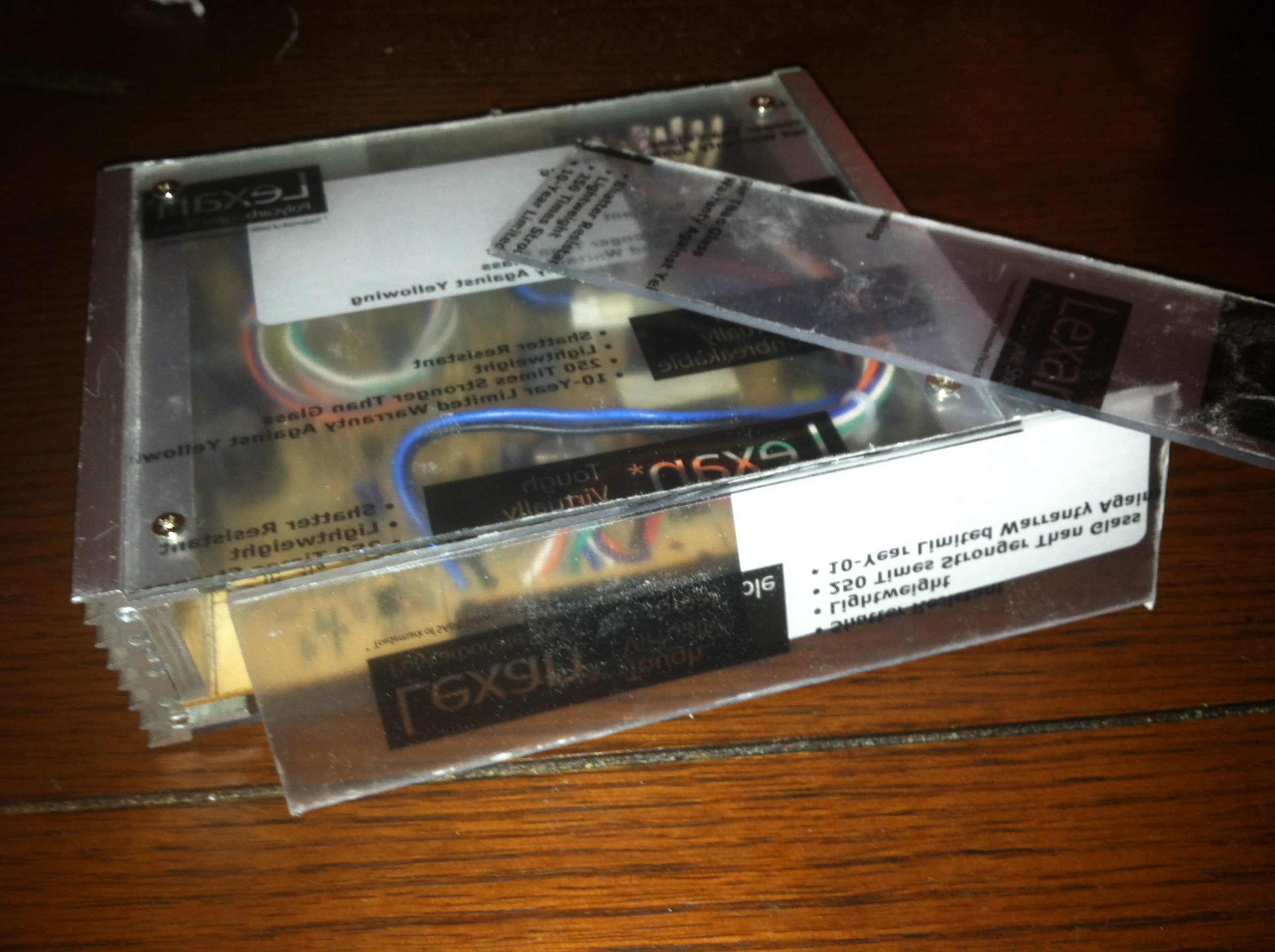
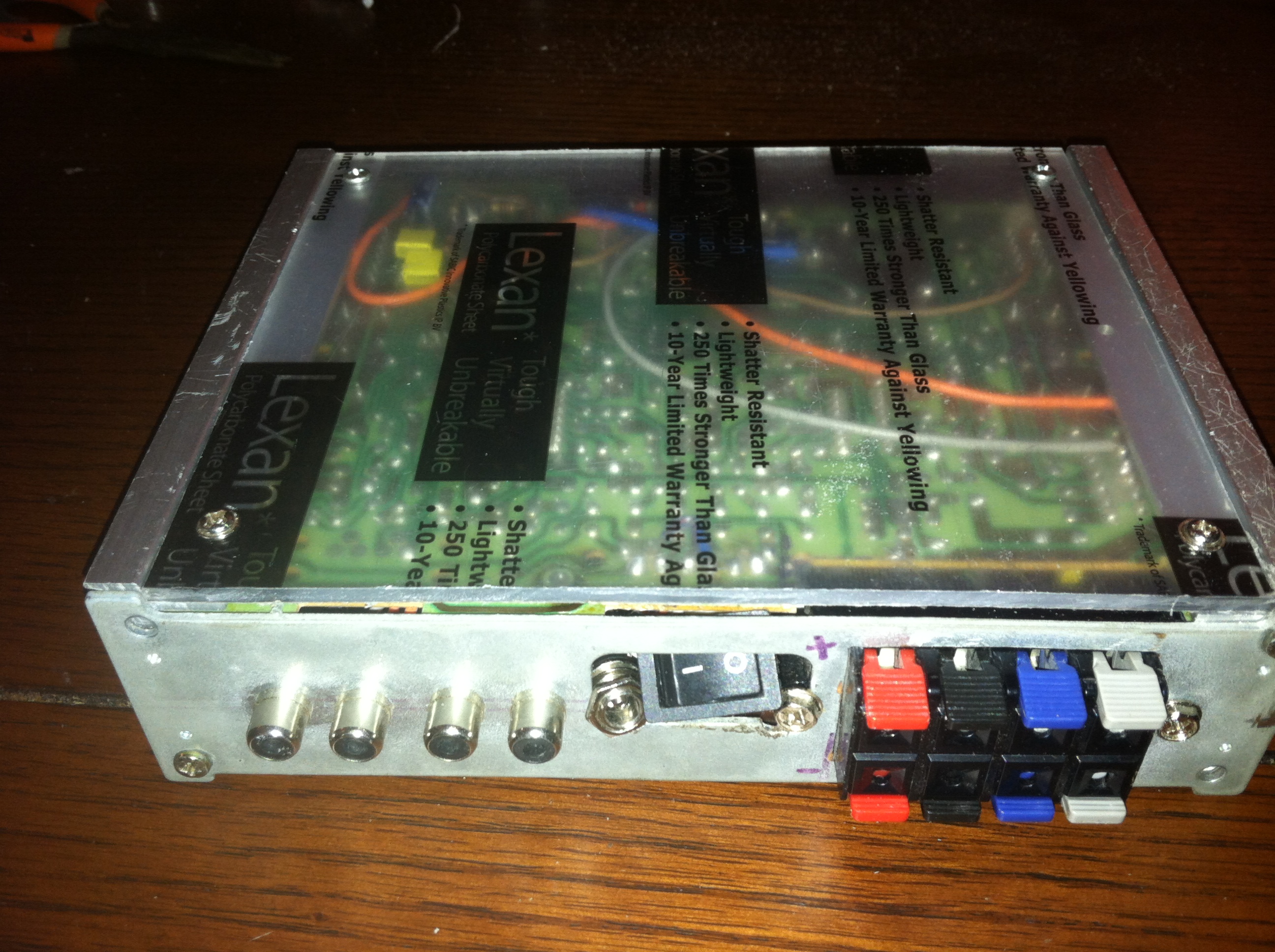
Here are the top/bottom plates bolted on to the heatsinks that serve as a frame for the amp. The rear plate will also be cut from the lexan giving a 4 sided window showing the insides of XodusAmp Redux.
Getting 5 volts
Sometimes its not clear exactly where a project started getting over-complicated, this is that moment. This would have been a good stopping point if I only wanted the unit to be an amp and nothing more. Since I like my projects to consist of more than just replacing metal plates with plastic ones I decided to add a microcontroller inside the amp. Specifically in this case I am using the Arduino compatible Teensy by PJRC, this wonderfully small and powerful dev board will serve as the heart of XodusAmp Redux.
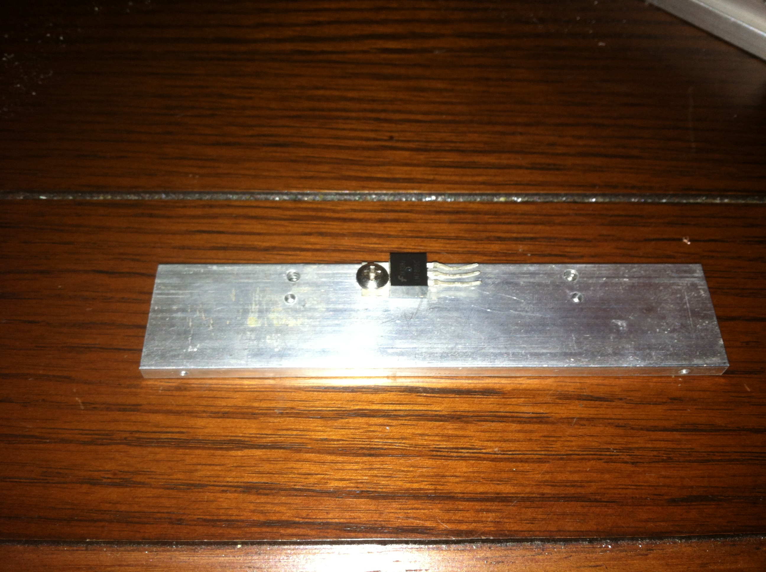
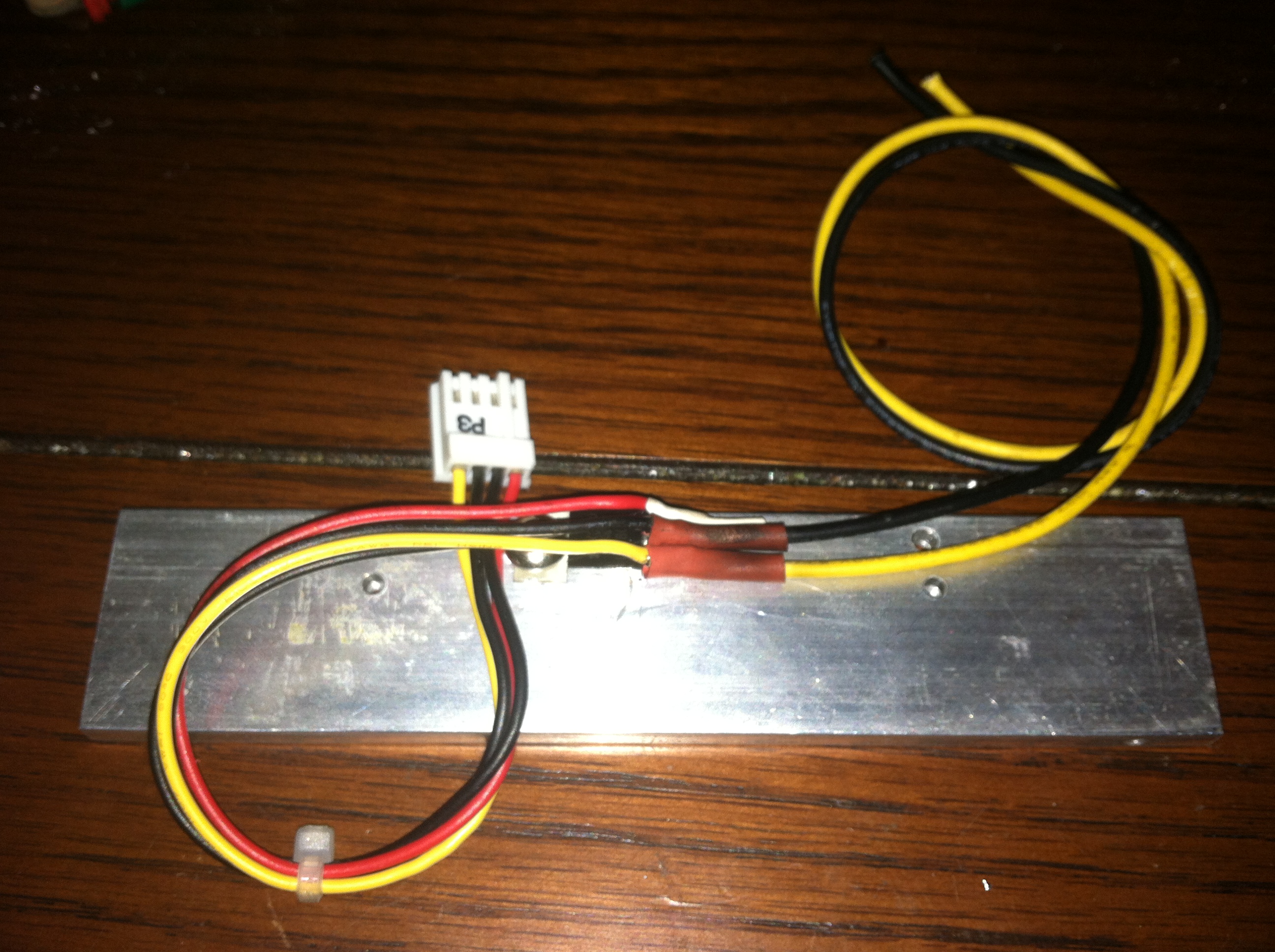
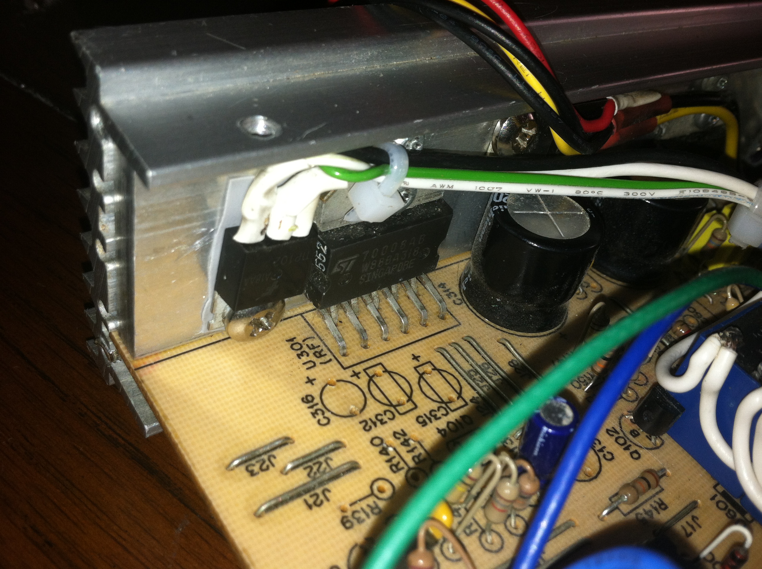
The Teensy like all Arduino’s or any microcontroller needs power, the chips generally run from 3.3v with most dev boards housing a 5v to 3.3v regulator. Here I use a 7805 linear voltage regulator to step down the 12v input voltage to the 5v needed by everything else but the amp itself. The regulator was mounted to one of the large heatsinks in the amp to prevent the regulator from burning out under load.

Being a big fan of modular connectors I used a standard floppy molex connector to deliver the power from the regulator to my microcontroller. Here you can make out the yellow/black wires as input and the red/yellow/black as output.
2/4CH Input Selector
One thing I have always disliked about the original Xodus Amp was that in order to use all 4 speaker outputs all 4 inputs must be driven. Typically I would connect two sets of RCA to phono cables between the amp and my computer giving me 4 channel surround. Now that I will mostly be using the amp with 2 channel sources I would either need two RCA y-splitters or a switch that sent the signal of the first two inputs to the second pair of inputs respectively.
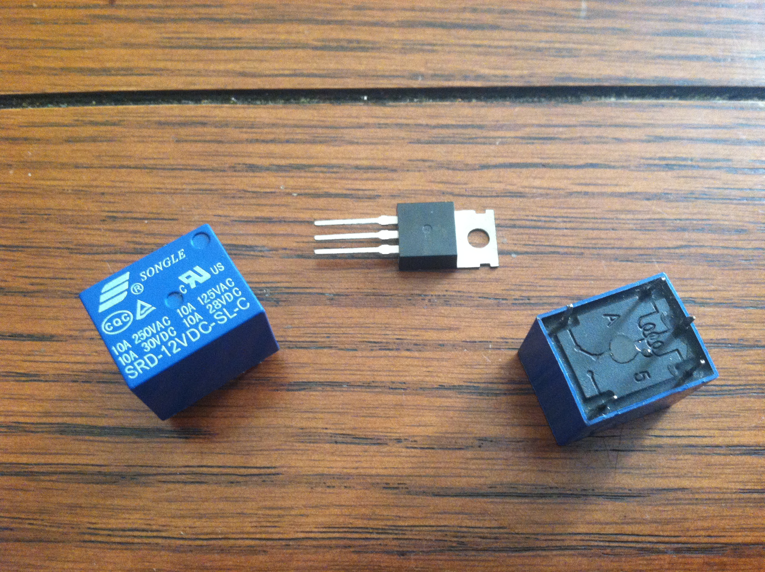
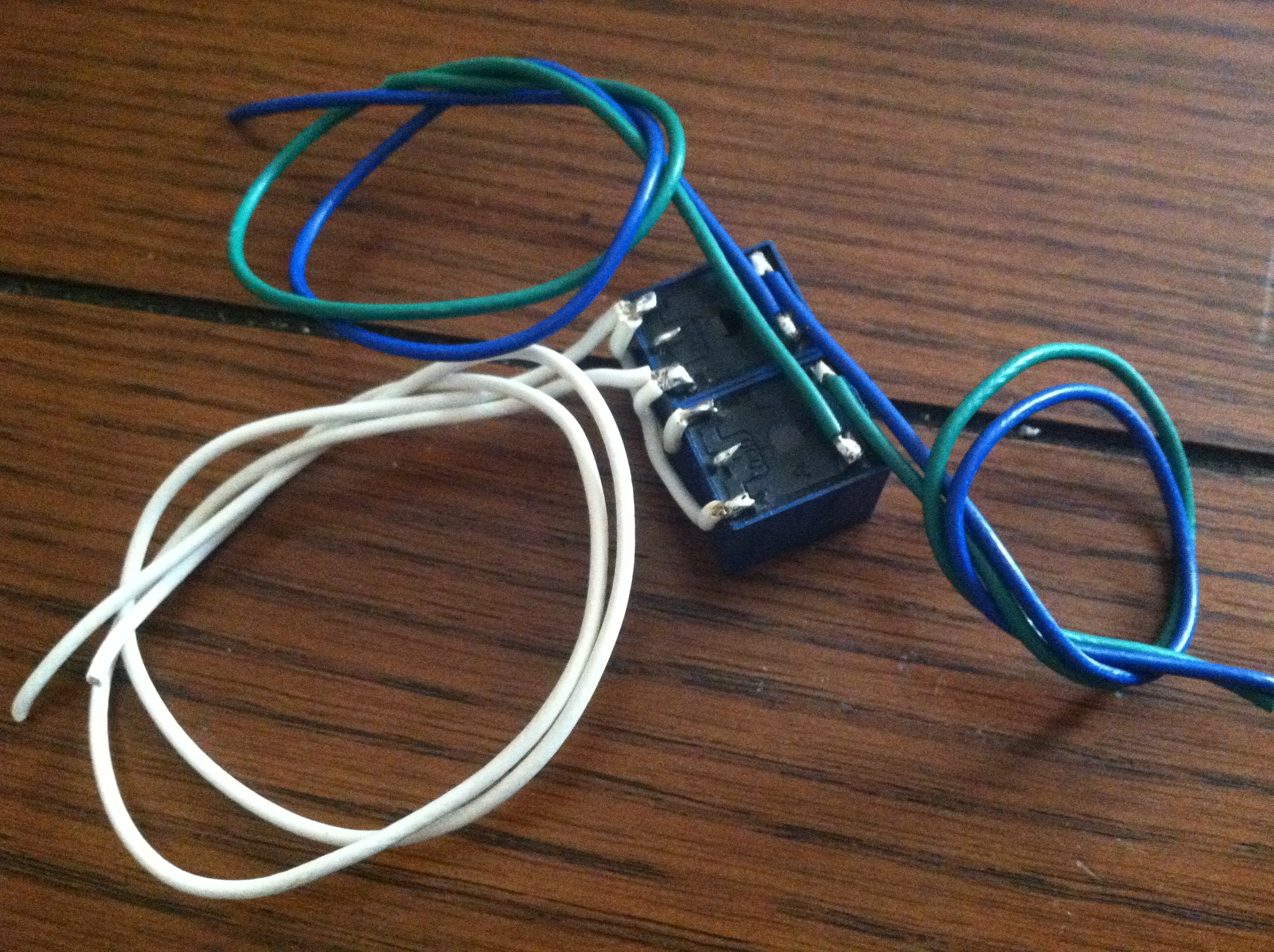
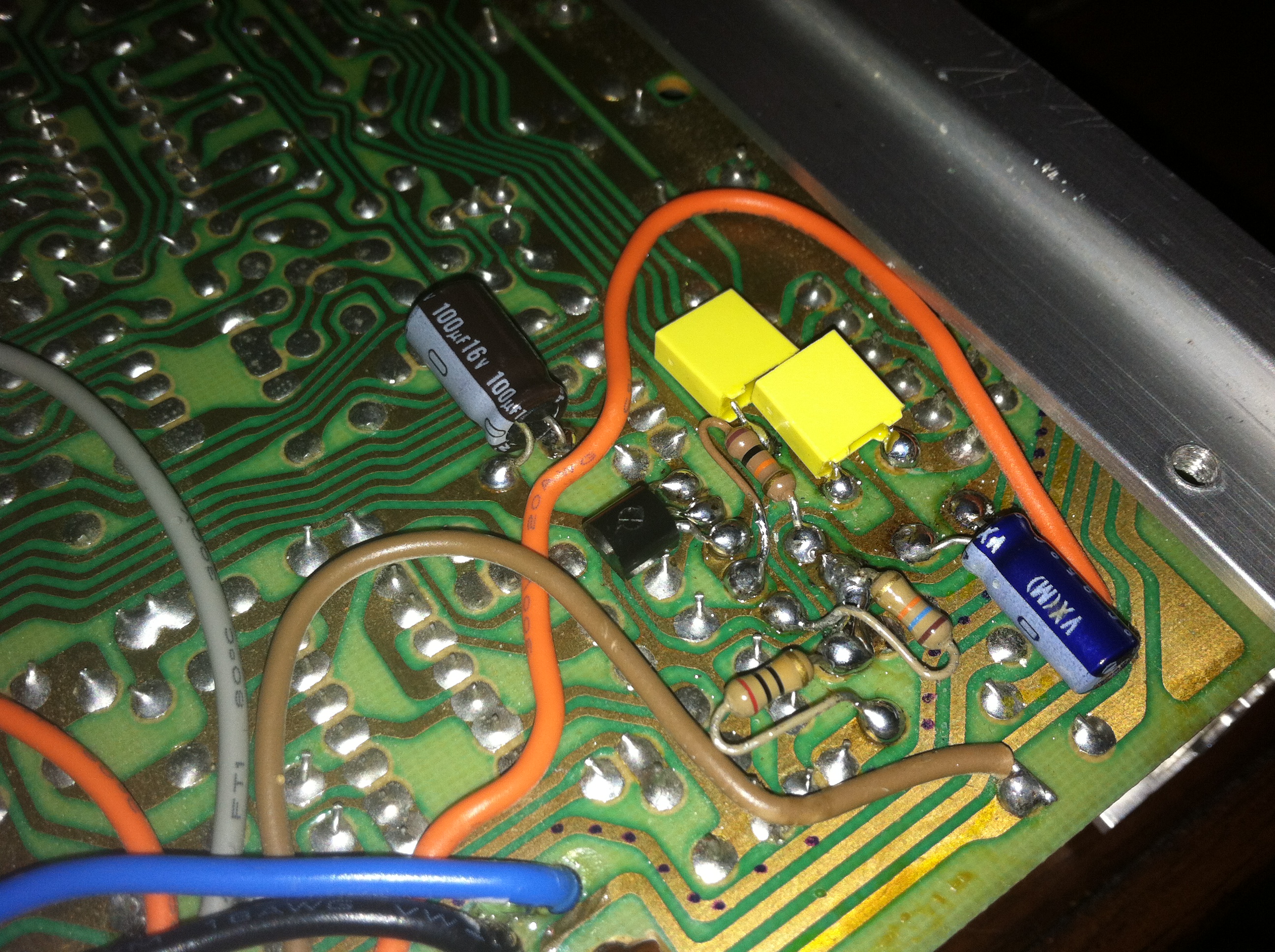
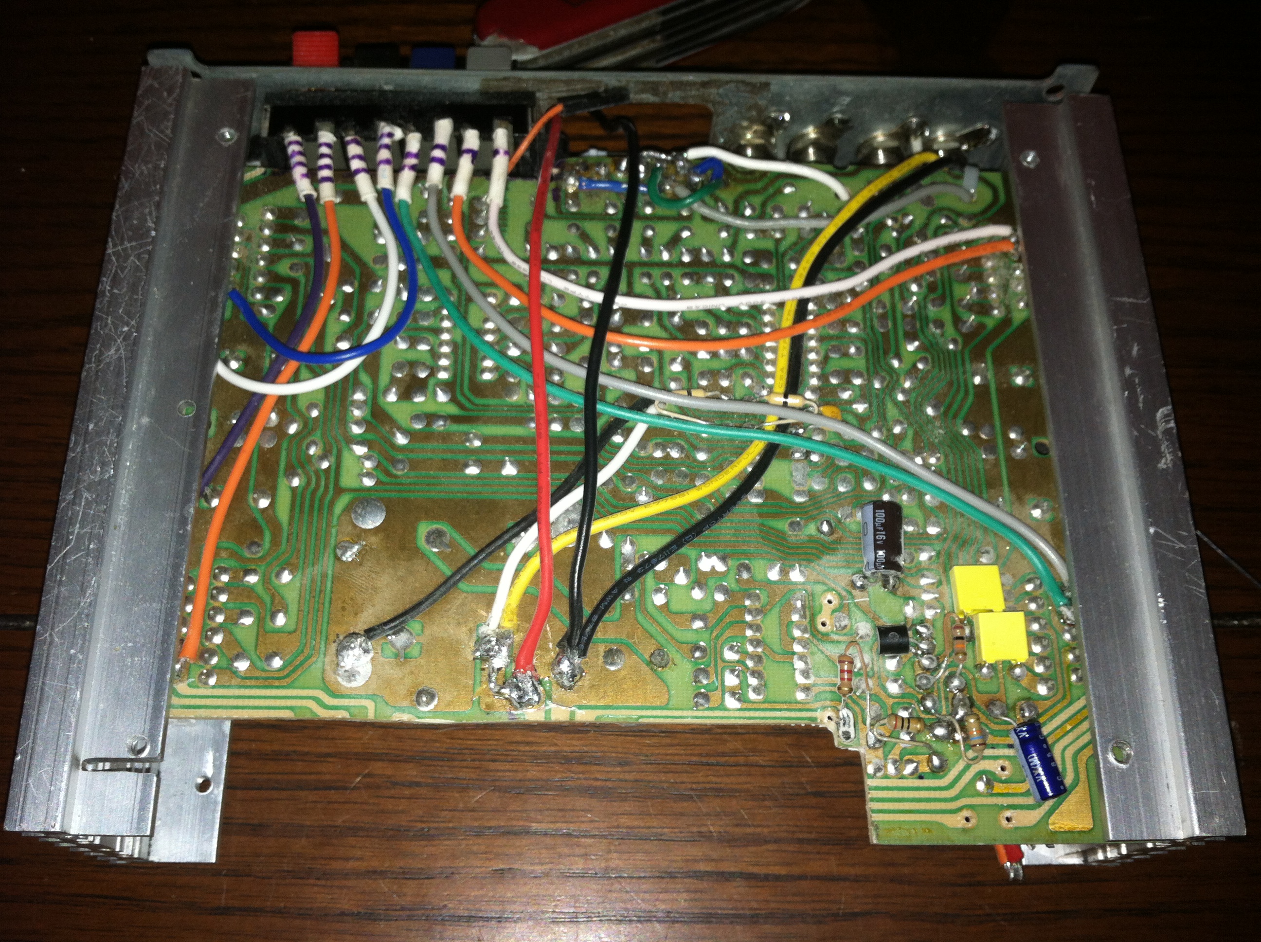
When building projects its easy to accumulate extra parts that you can use in the next. Here I found 2 relays and an NPN power transistor that I bought for the WiFi Traffic Light project. First the 2 relays were glued together and wires attached. The coils were wired together in parallel so I can drive two relays from one transistor.

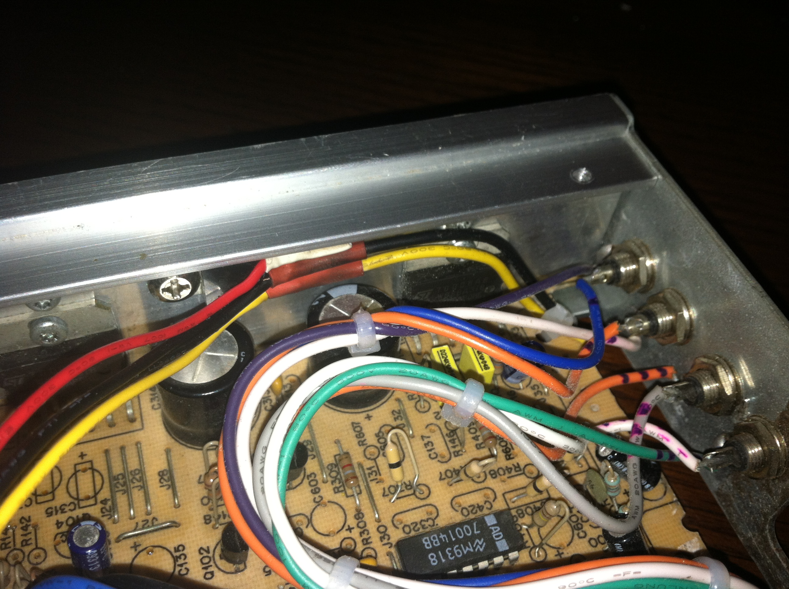
Same as the 7805 regulator the NPN transistor was bolted to the heatsink, here I had to use an insulating thermal pad between the transistors mount and the heatsink. Next I cleared another spot on the amp board by relocating the components to the underside of the board. The relays were then wired into the amp’s audio inputs and to the power connections on the bottom.
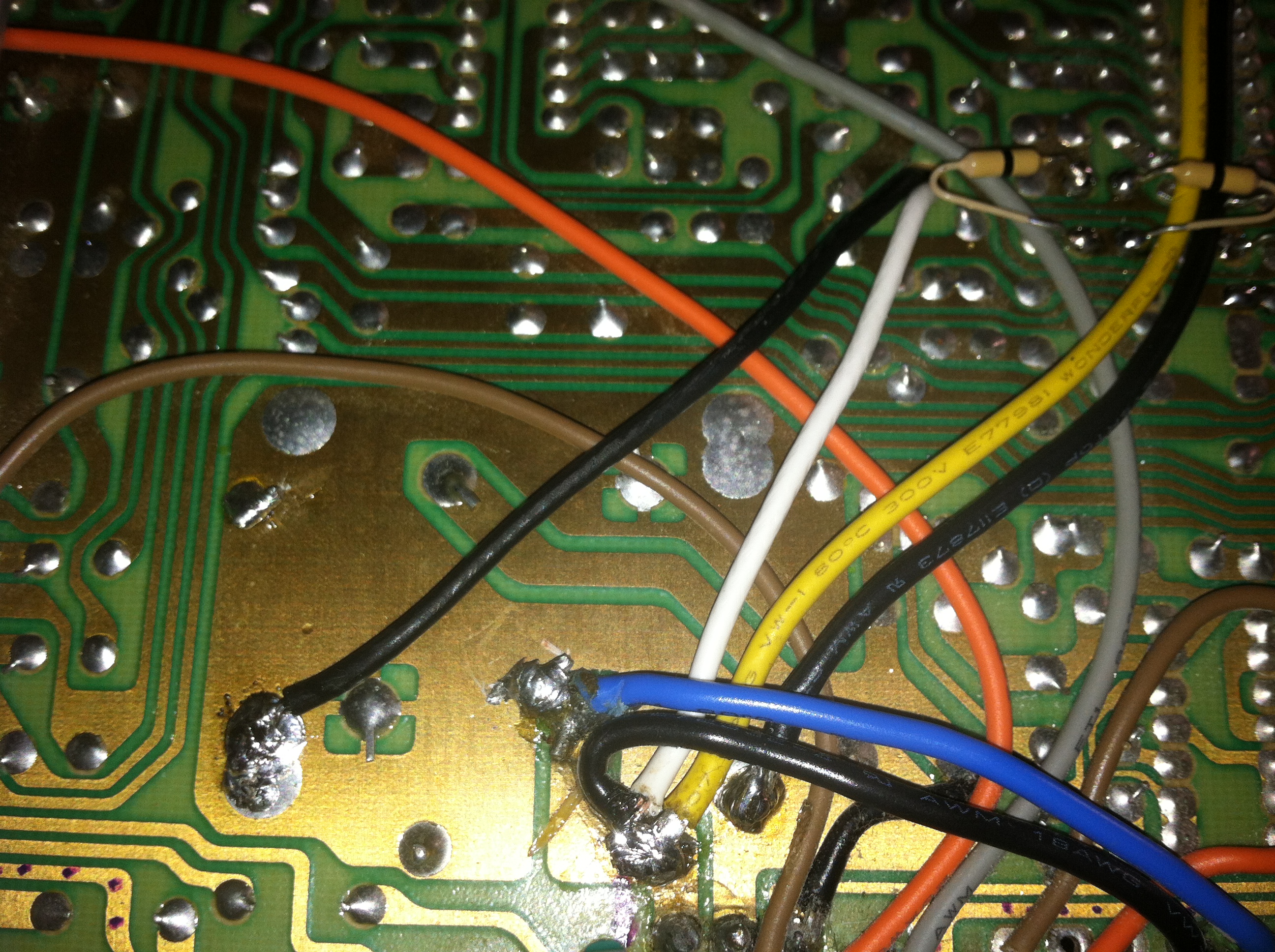
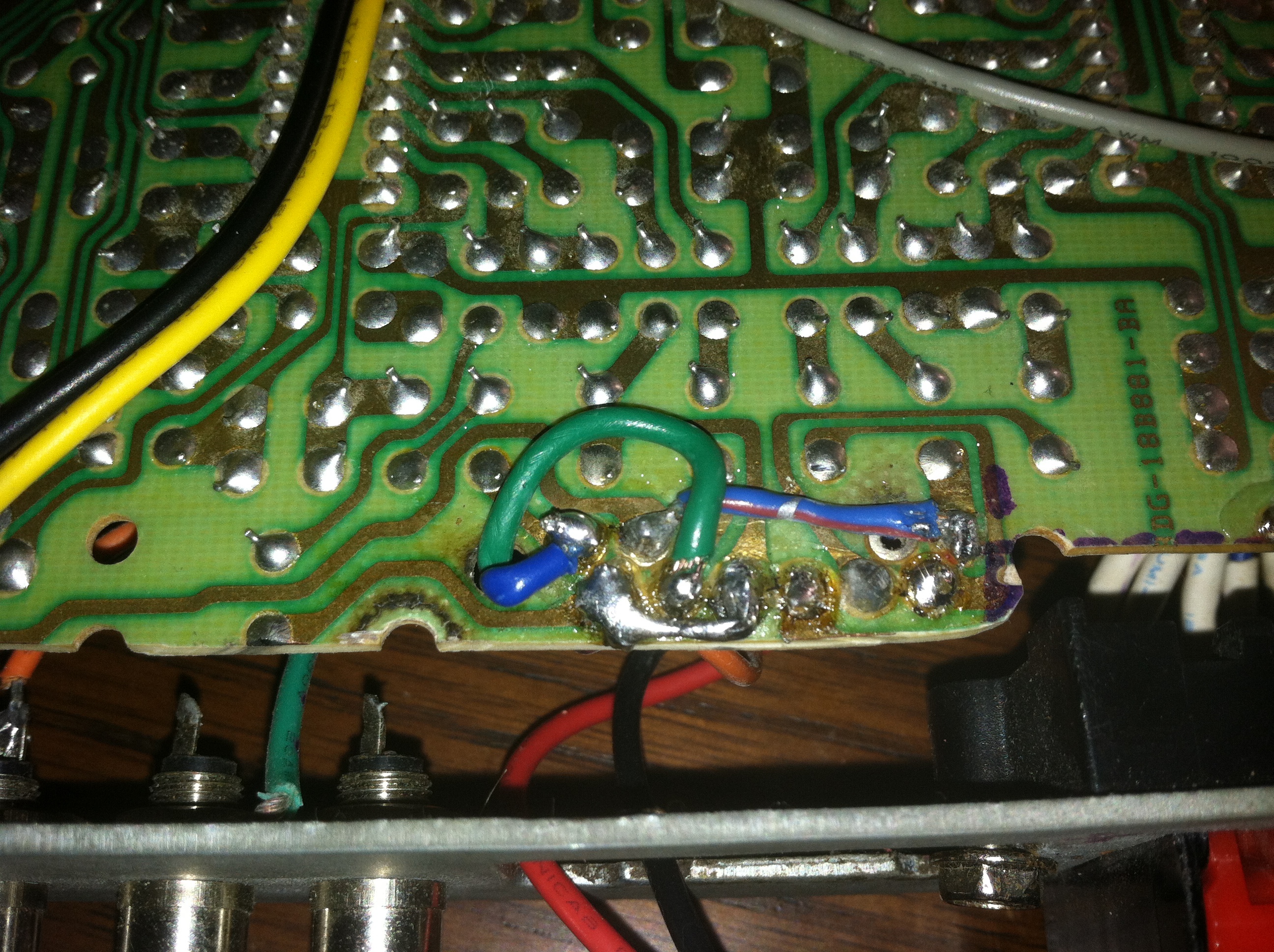
Here are the additional connections made for the relays to act as the input channel sector and the two resistors that were relocated to the bottom.
Samsung VFD and Controller
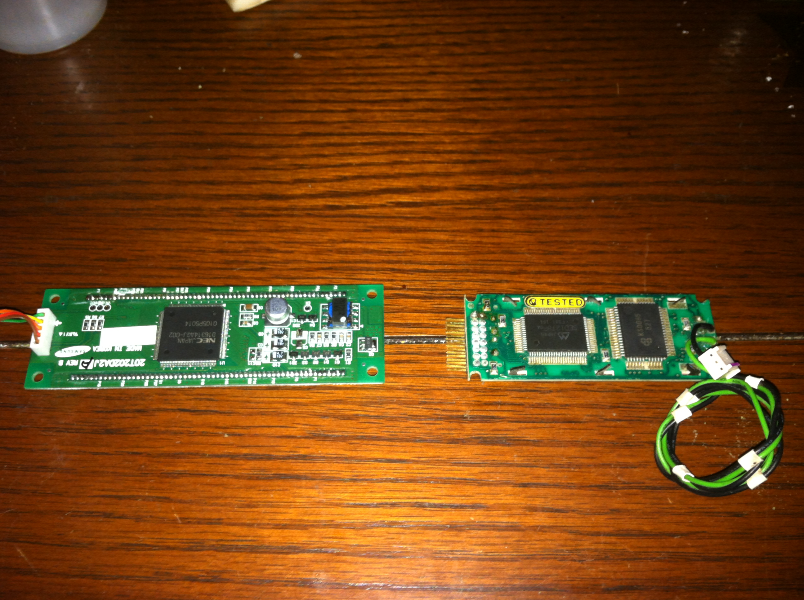
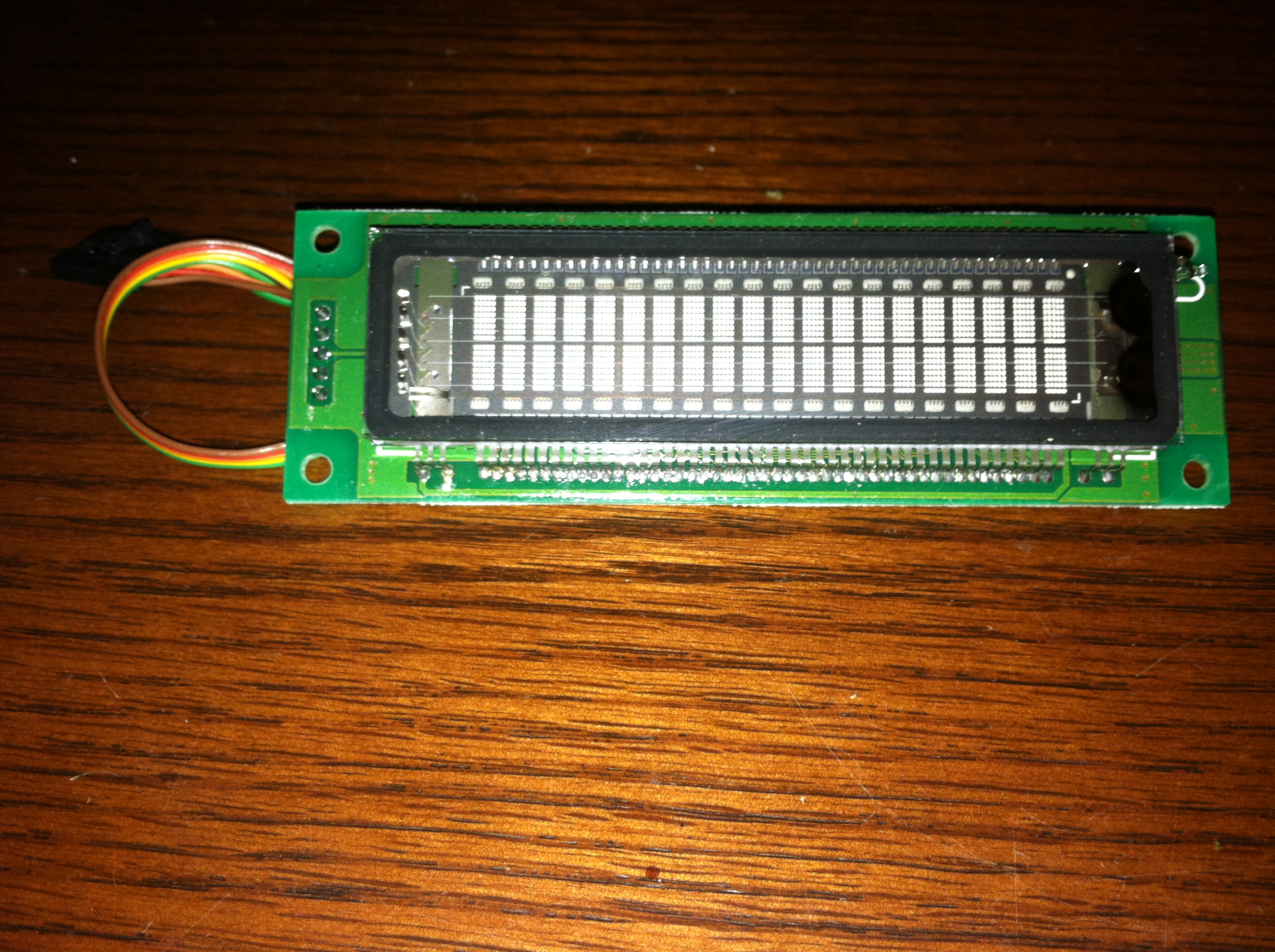
Delving into the meat of this project we come to the controller and the new display screen I will be using in XodusAmp Redux. The wonderful and stunning Samsung 20T202DA2JA 2×20 VFD was chosen due to its compact design and simplistic interface. Having connected too many HD44780 parallel LCD’s to things having a 5 wire serial interface versus a 14 wire parallel interface. Although the VFD is a bit pricier than a traditional LCD they look great and will help bring a sort of audio pro-gear feeling to XodusAmp Redux.

Compared with the original screen the VFD is considerably larger. Some of which is accounted for by having 4 extra characters per line on the VFD.

First I connect the new VFD to my breadboard using my favorite breadboard Arduino the Boarduino, a breadboardable Arduino clone.
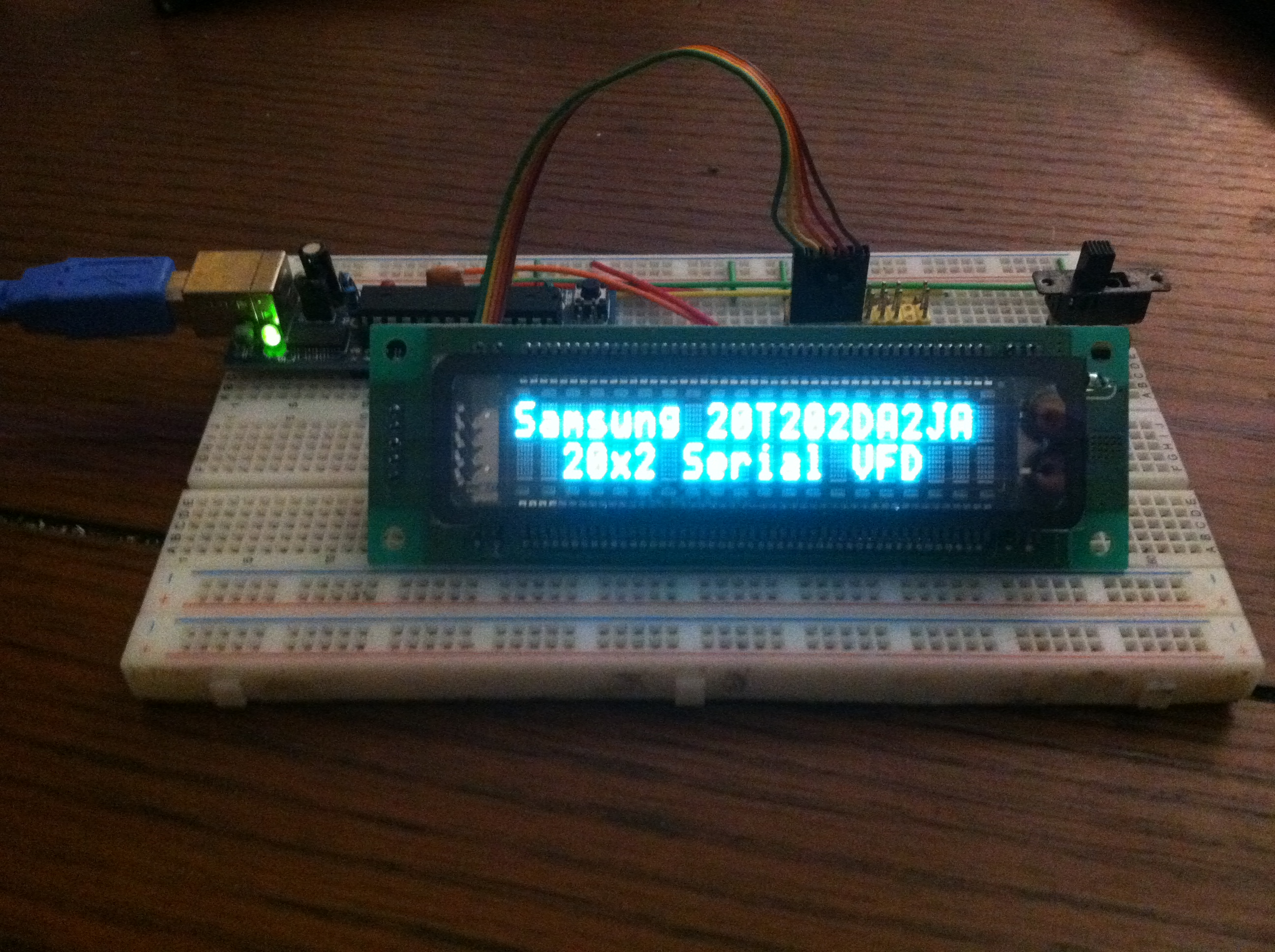

Using some sample code from the eBay auction for the VFD I was able to get text showing on the screen in no time.
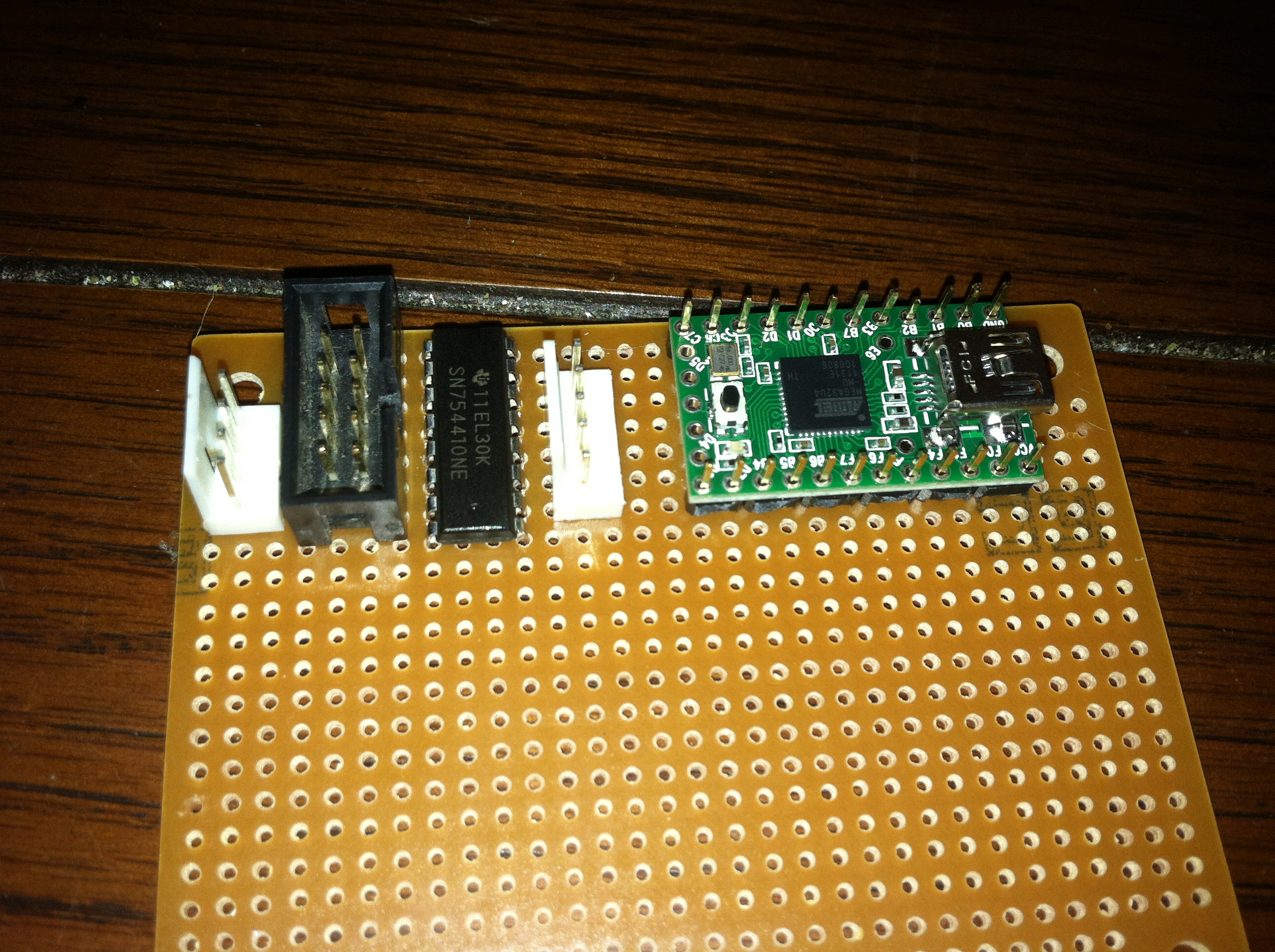
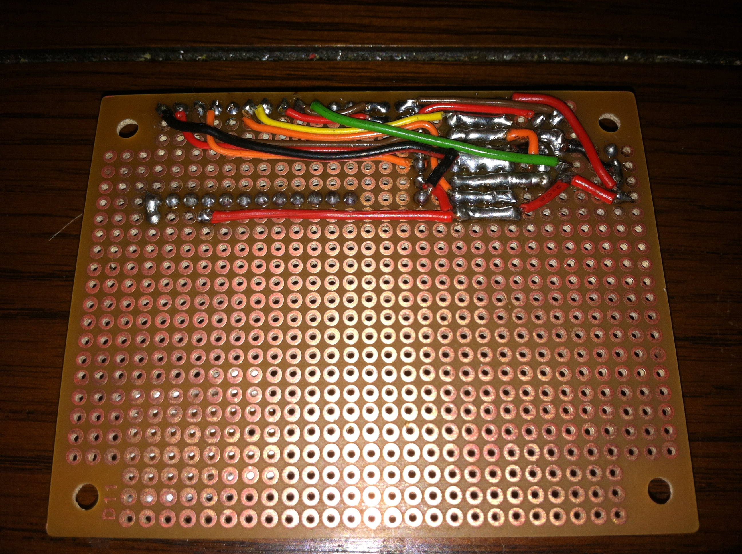
Next I had to design a small board that will interface with the VFD and the other components in XodusAmp Redux that will be controlled using this controller. First I lay out the connectors in the smallest amount of space possible. The 4 pin connector is for power, 5 pin is for the VFD, and the 10 pin connector is for the Potentiometer Motor, Channel Selector, Power Control, and the IR Receiver.
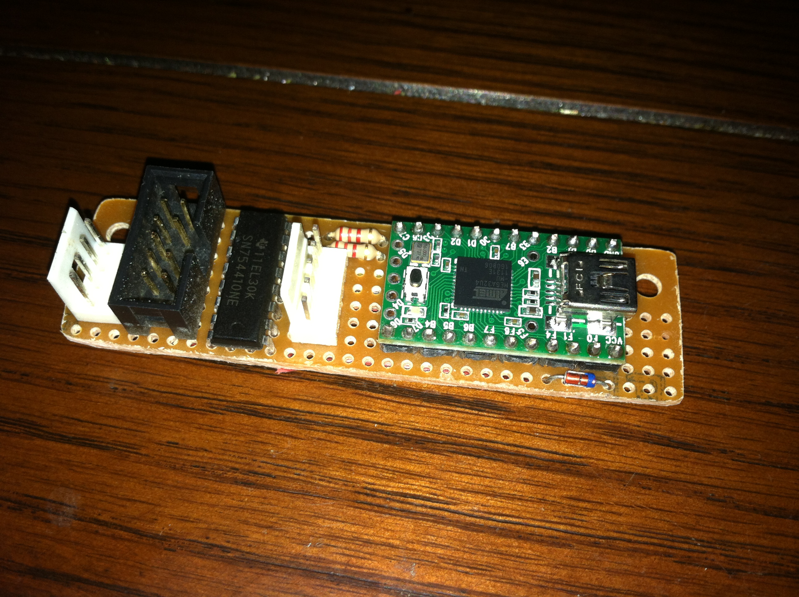
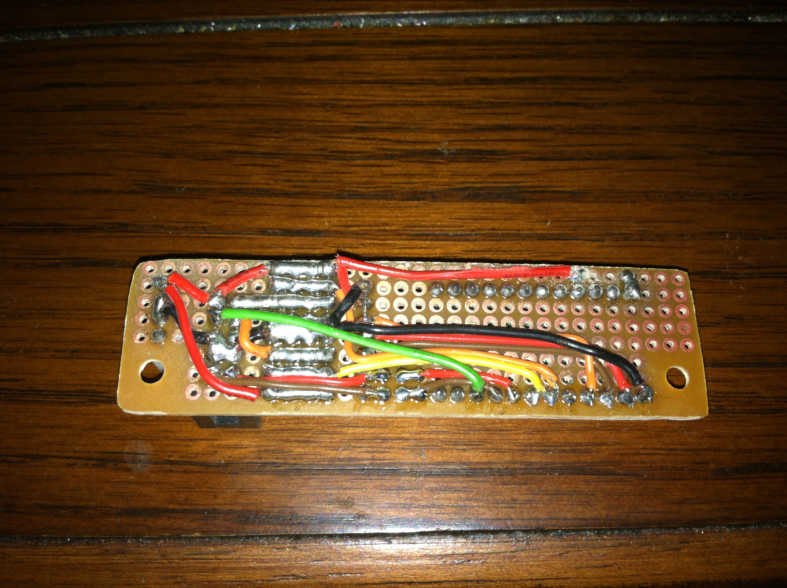
With all the connections soldered the board was then cut down to a more manageable size.

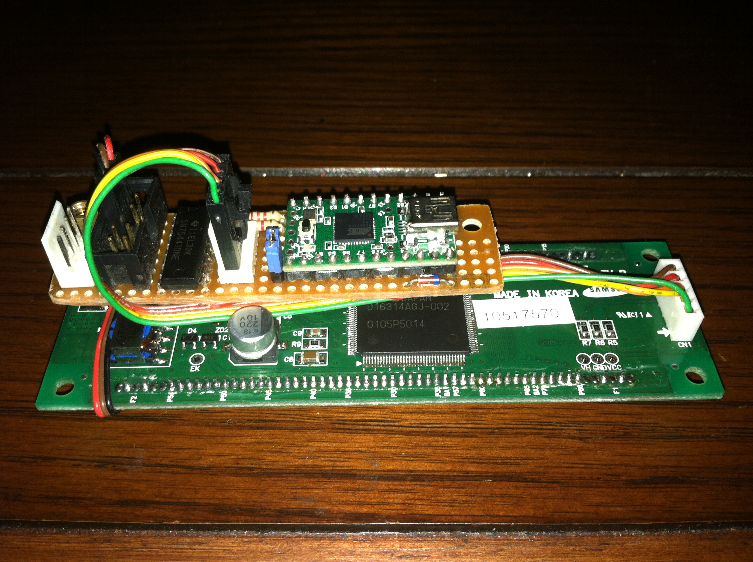
For mockup purposes I attached the control board to the back of the VFD, this is how it will be mounted in end.
Mounting the VFD Screen and Controller
The new VFD screen is quite a bit larger than the original LCD screen more PCB area needed to be removed to accommodate the screen on the front of XodusAmp Redux.


As a prelude to removing more of the original PCB the speaker output wires needed to be relocated. Since the only purpose of the speaker output connector was to connect to the individual pins on the amp chips a bit of point to point soldering eliminated the need for the area the connector was originally soldered. At the same time a few traces were eliminated that were no longer necessary.
Next the power wires were moved and connected in the original equipment configuration to regain the usage of the ACC (Amp Enable) line. The area was then cut from the PCB using a Dremel and a small notch placed in the heatsink which will hold the edge of the VFD screen board and serve as a guide for mounting.
Putting It Together
Finally with the major electronics it was time to concentrate on updating the exterior of Xodus Amp Redux.
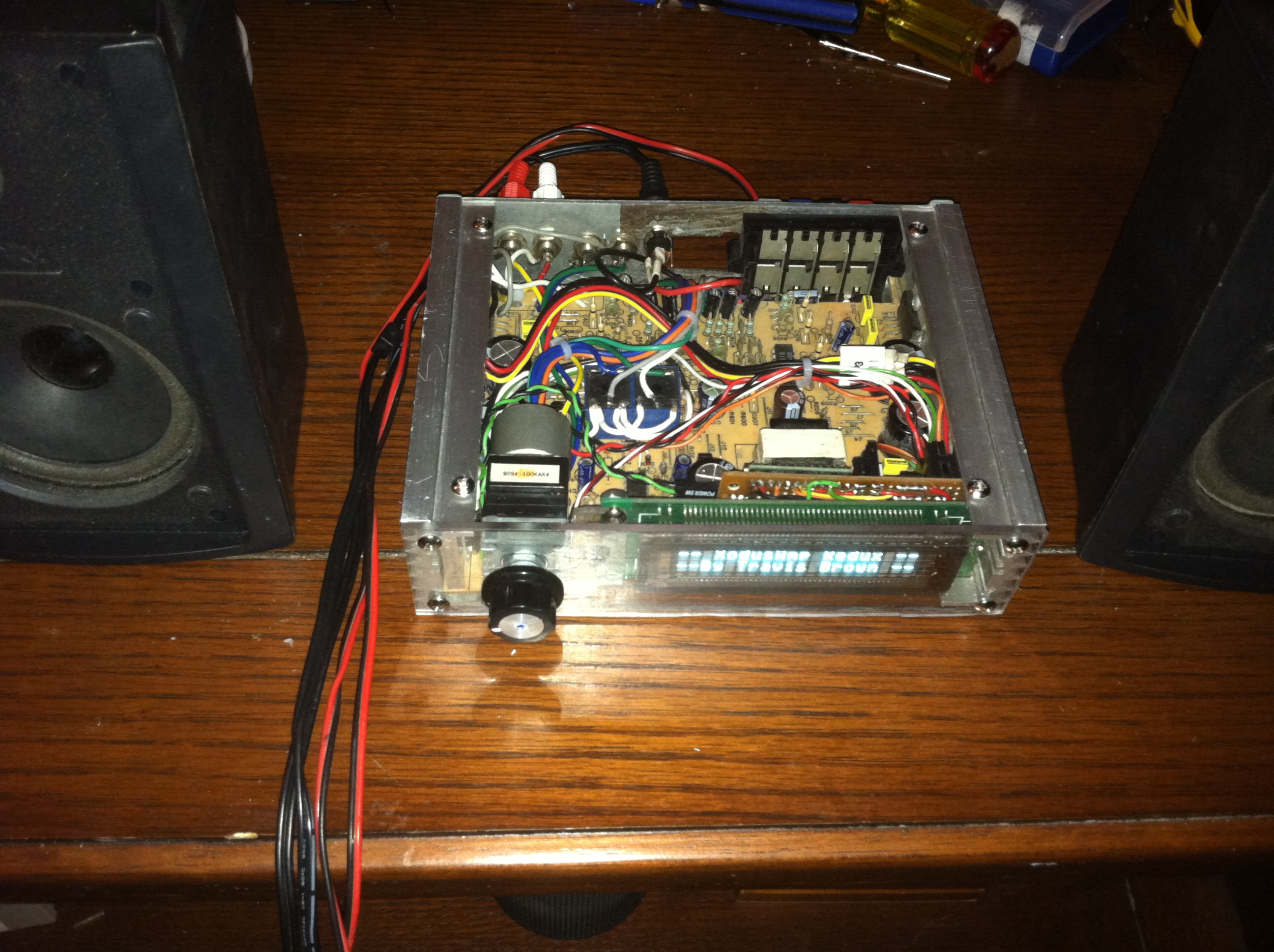
The above shows an overview of the layout of all the new electronics including the motorized potentiometer , the VFD display, and the Teensy driven control board. The AMP On wire from the original amplifier is now switched from the control board giving the user full control over power, volume, and channel selection from the remote control or through USB.
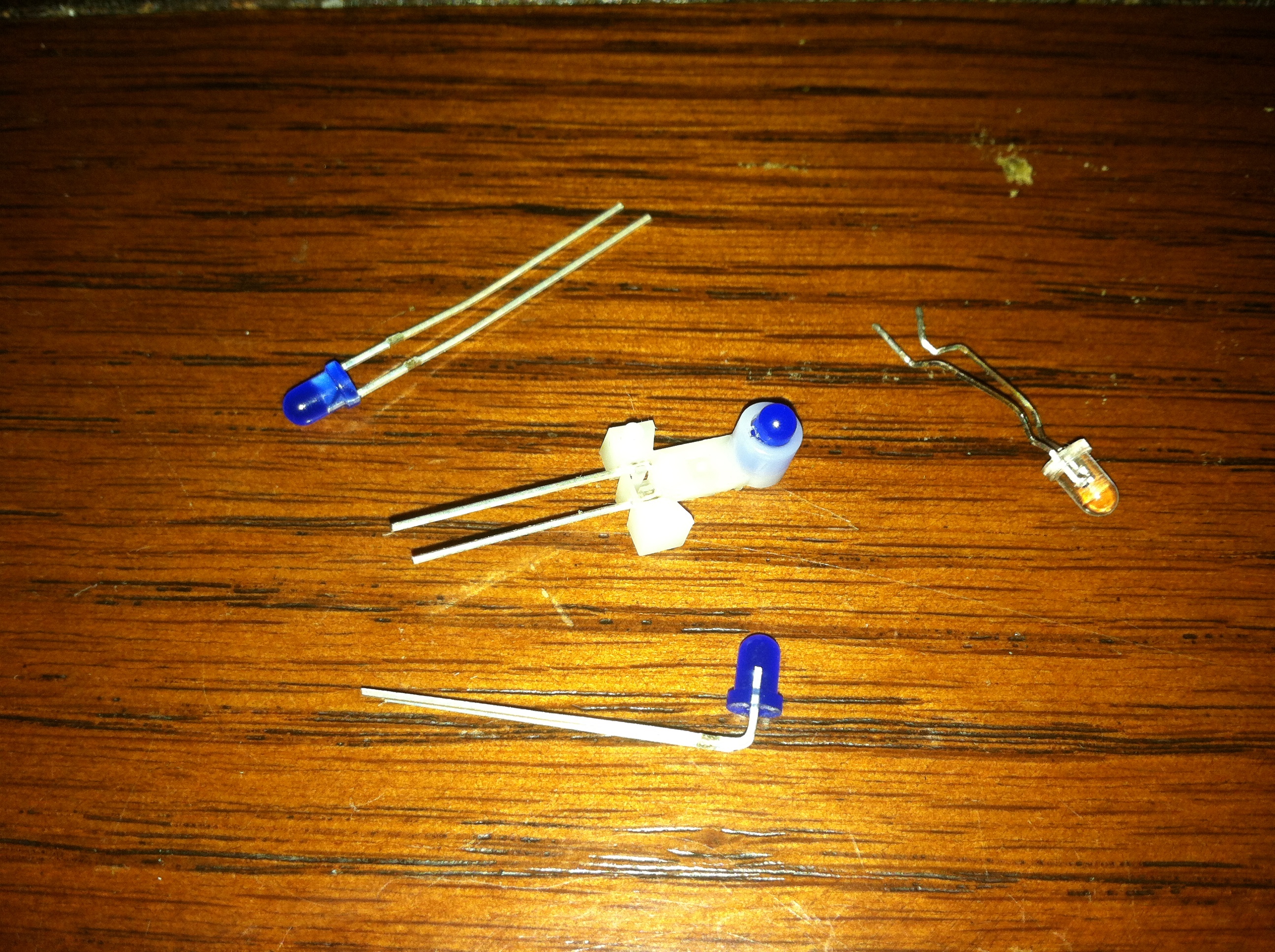
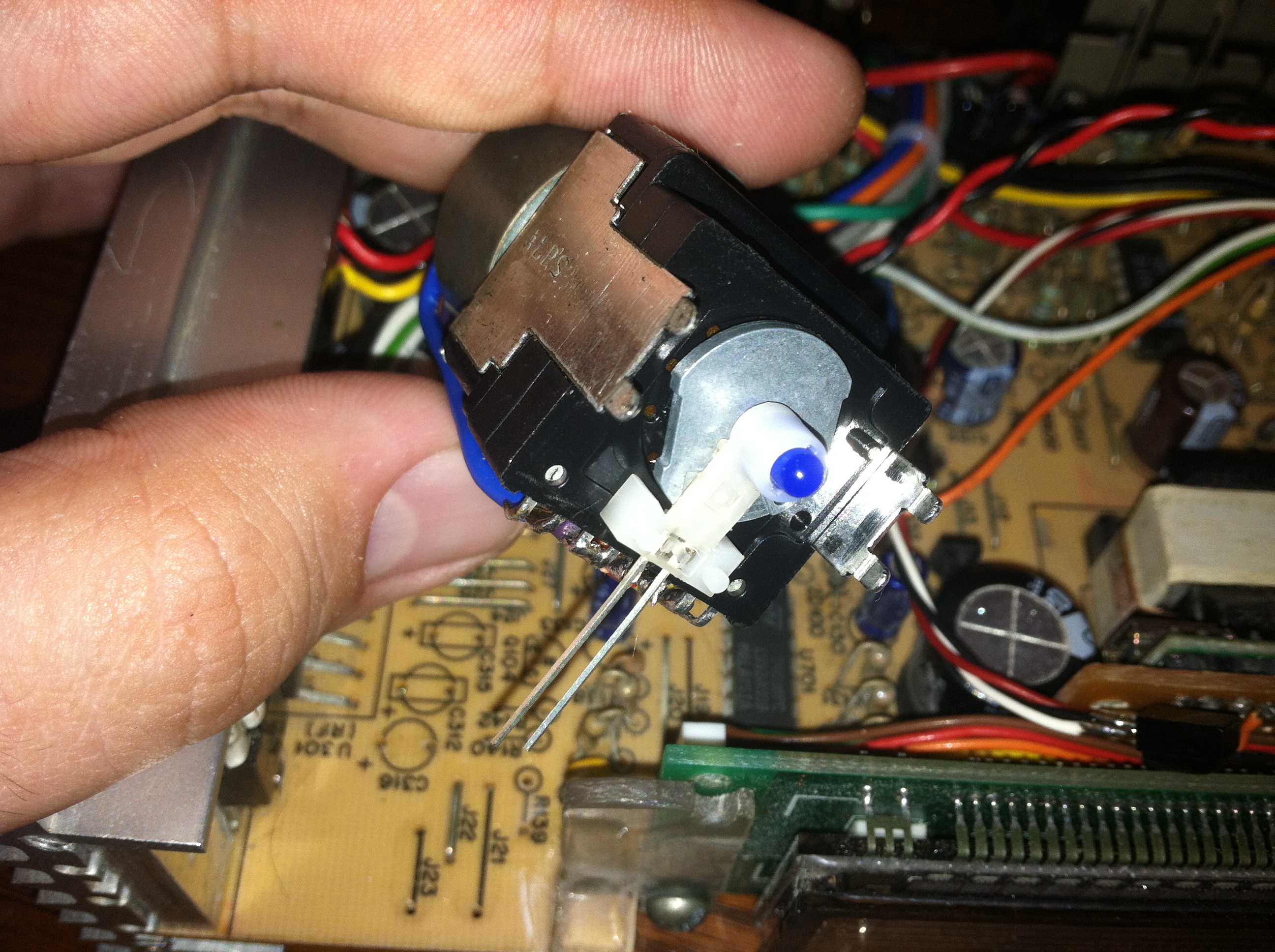
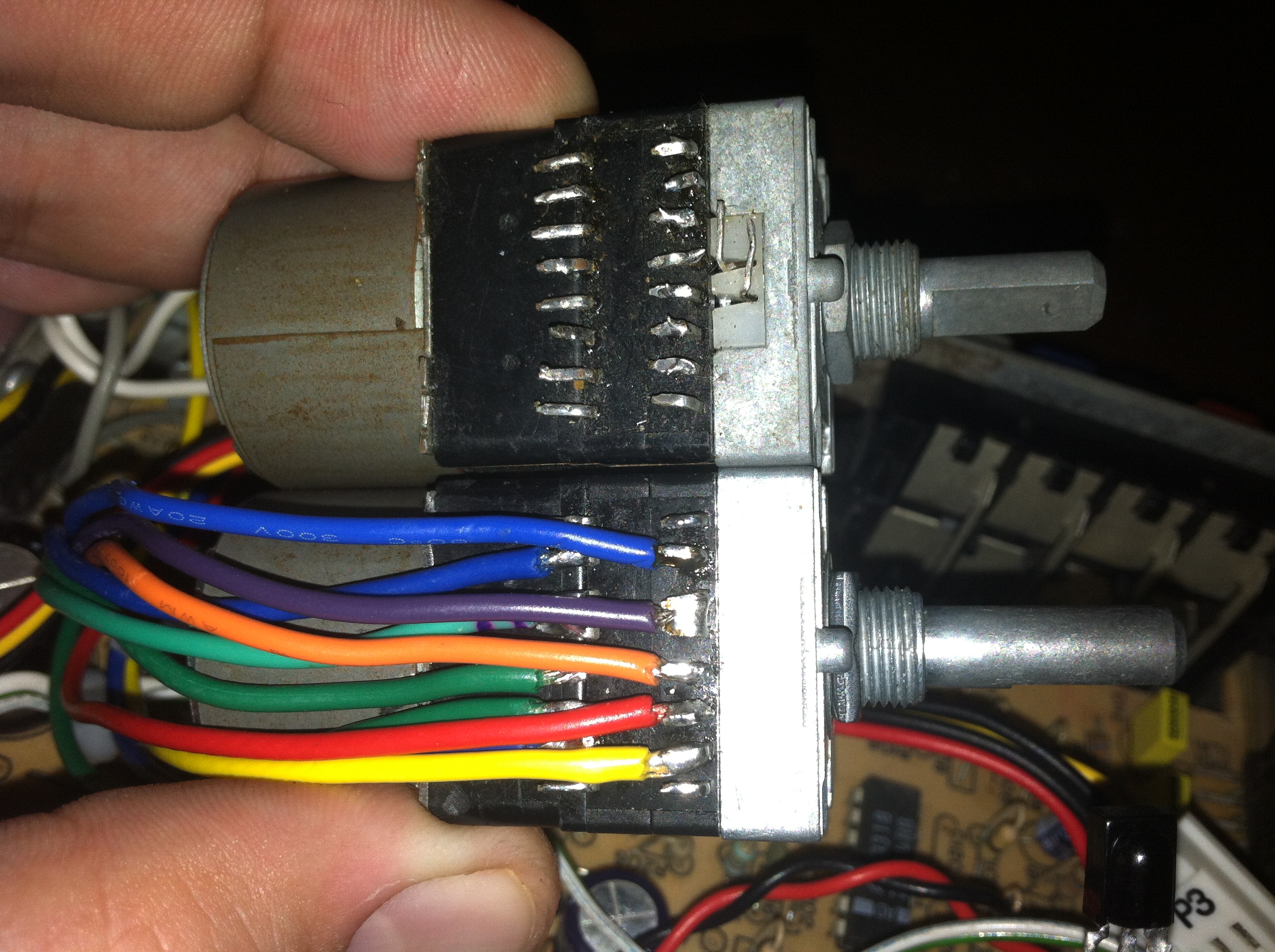
The new potentiometer did not have an LED like the one from my parts bin however upon further examination I realized I could use the front shaft and LED assembly from the strange potentiometer from my parts bin and upgrade the new one. What is truly amazing is that 20+ years later ALPS has stuck with their design. I could have actually used one of the dual channel PCB boards and metal contacts from the new potentiometer to upgrade the older one but I thought it best to use the newer drive motor and double dual channel pcbs and brushes.
Now the top and bottom plate could be cut and all clearances checked to make sure everything actually fits within the enclosure without rubbing against the plates as that could cause scratching or if the item was hot could cause warping.
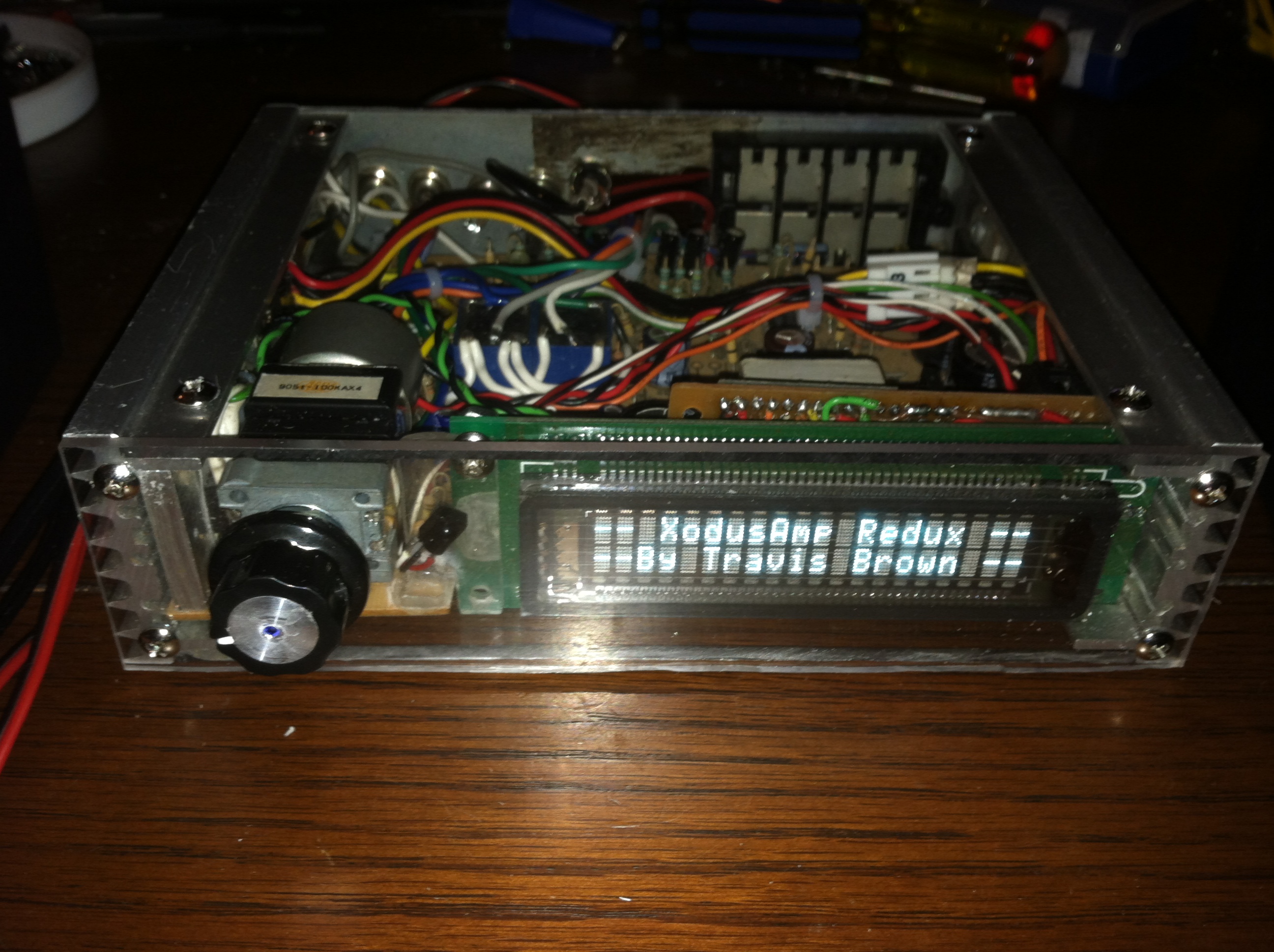
With the front plate cut the excitement of seeing what it would finally look like got the better of me so off came the protective overlays. The Lexan is so well polished that it literally looks like there is nothing between the inside and the fingers of curious passers-by. A small hole was drilled in a random knob from the parts bin just to illustrate the design and to give the unit a run through while rocking some tunes, my screen name is after all WarriorRocker 😉
Parts List
- Samsung – 5 Pin Serial VFD
- Teensy 2.0 – Arduino compatible mini development board
- ALPS RK168 – 4 Channel Motorized Potentiometer