Description
Introduction
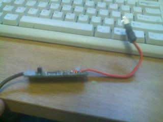
In my shuttle (sb61g2v4) silver xpc, I only have 2 serial ATA ports, granted they are only SATA-I it is still sata, not the speed that is important to me as the sata itself. Well I originally had 2x250gb drives in the machine each on SATA, so there are the two ports.
I recently added a 500gb SATA-II drive, now that leaves a problem. 3 drives 2 ports. so i purchased at the same time a small external sata sata usb controller. Problem is A) it was external, when I wanted the drive internal. B) It had an ugly usb wire on it c) It also had a soldered on sata cable.
This would not do, So it was time to open it up and do something about it. A few weeks ago I replaced the usb cable it had with one that would plug into my shuttle’s motherboard (it has several headers for various other devices shuttle could have one day made or included inside, one of those being the shuttle wifi adapter).
Phase I
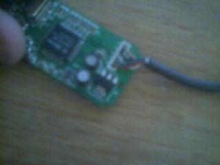
This worked okay. But I was still not pleased with the short and ugly SATA cable soldered onto the board, so I also desoldered that and soldered on a real sata plug. I had desoldered a few from a fried motherboard not long ago. I did this because I want to route the controller out of the way, with a real cable that can be removed, replaced and the likes.

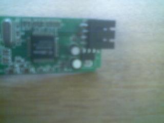
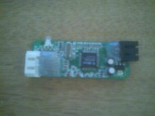
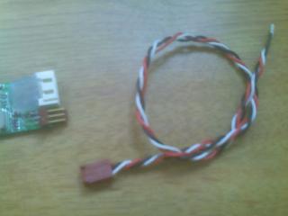
Some shots of the cable that was soldered on the board. This cable is far too short for the project I have this destined for and must be removed.
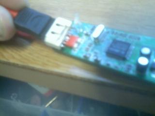
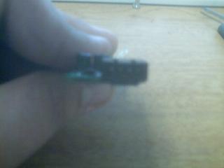
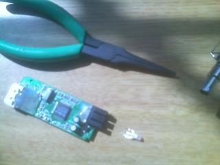
Lining up the new connector, and then the desoldered SATA cable.
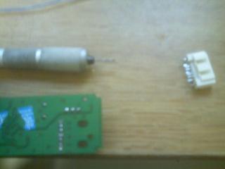
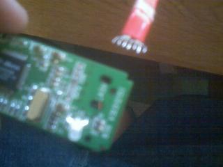
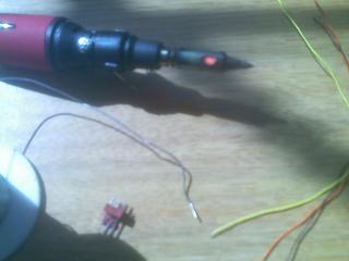
Using my mini hand drill to drill through the solder contacts for the SATA.
I had to extend the contacts to reach my connector, as I would be mounting it at the edge of the PCB, So I used some single core wire (single core because thats what the SATA wire used, and its the easiest to move and bend and make it stay that way).

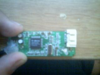
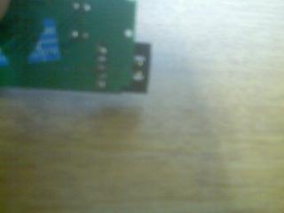
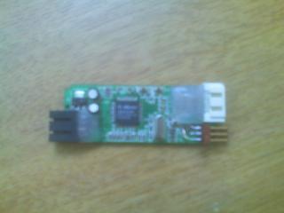
Just some glory shots of my new connector, I glued it down with some super glue, it should hold there for quite some time. I was kind of scared to be messing with SATA, but like benheck said: “I was worried when I read SATA doesn’t use TTL, but apparently it doesn’t exactly use magic either, so it’s still hackable”.
Phase II
What I went ahead and did was solder on a new usb header, As I love things to be modular, plus it makes it way easier to work with down the road. First I had to remove the old usb cable I had soldered on there.
Using my mini drill I drilled out the solder holes for the usb. This makes a great alternative to solder wicking when applying extra heat to the board is a bad idea.
This is where I ran into a small snag. Recall that most usb is wired (Red, White, Green, Black), this controller was wired for (Red, Green, White, Black) PROBLEM!, as I like to use and abide by the wiring standards, also I can easily plug in other things there that use the same wiring pattern. So I had to use the same technique with the sata to extend the wires off the board so I could solder the connector flat, while running the wire I crossed the two lines.
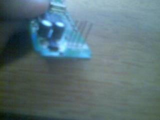
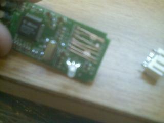
Shots of the wires I soldered to the board, and the connector I intend to use.

Connector all soldered and plugged in.
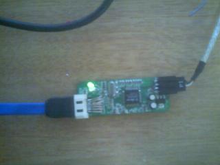
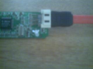
Glory shots of it plugged in and working like a charm.
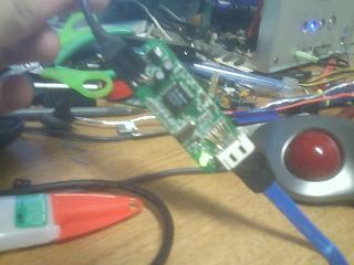
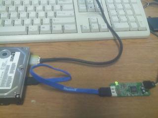
The board plugged into my shuttle’s motherboard and online.


One last shot showing the board all glued up.
Phase III
I decided to move on with the header to break out the LED signals. I decided to use a standard fan connector for this, for 1 of 2 reasons, a) I have like a thousand fan connectors, b) the plug will only go on one way, this makes sure that the activity and power sides don’t get reversed.
Originally I was going to put the led header on the side of the pcb with the usb header. I eventually gave up (after destroying a fan header) and decided to put it on the same side as the sata header. Originally I was going to use parallel port wire to relocate it, but since right next to the SATA header was the led solder points, I just used some single core cat5 and did the same thing as I had done for the usb and SATA port soldering job.
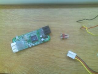
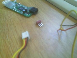
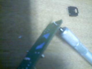
SATA board and the fan header I planned on using.
Desoldering the Power/Activity LED, and the original connector relocation.

Original Idea, vs what actually took shape on the board, soldered connector flat just because I hate things that stick out and make the shape oblong and weird.

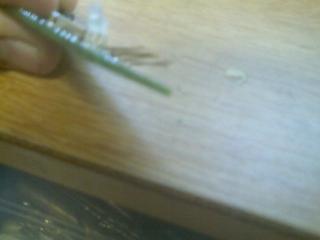
Pictures of the cable that I will use to connect to the led header. Also I decided to twist the wire together, it was kind of squirrelly?, Amazing what a dremel can do, cut, sand, and more importantly twist wire!