Description
Introduction
Let me introduce the LookSmart PC. The name comes from the HP TouchSmart PC, as this computer aims to produce a unit alike in nature to the TouchSmart, just minus the touch. The computer will be fully integrated to the back of the panel as you will see by the images. The board is moderately spec’d at 2ghz P4, 512mb ddr400, 80gb HDD. It has enough horsepower for fullscreen video and games like UT-GOTY and COD1. The monitor itself is a project as I was given it due to the backlight inverters being shot. More on that as the log continues.
This is a double project to find alternative means of driving the display and fitting a computer in there. These first two images are teasers of the direction this project will be going in. Hope y’all enjoy.
Rough Cuts
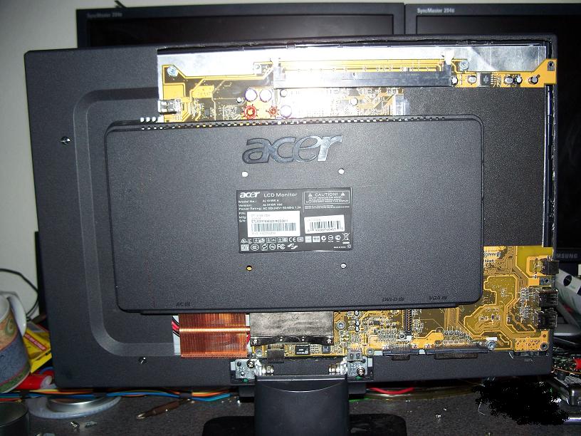

View of the back with the plastics cut away to fit the motherboard size. For this a piece of sheet metal was cut to attach to the back of the lcd and allow the motherboard to mount. Side view showing the cut away plastics and the edge of the panel. The goal is to not have to eliminate the large plastic covering the board. This will hopefully be usable for creating a casing around the rest of the motherboard. Ideas for that currently are leave it open, use plexiglass, or nice looking metal mesh.
Phase I
One of the drawbacks of trying to replace the inverters or powersupply in a flat panel can be locating power to drive your inverters and finding a way to have them turn on and off with the panel. The LCD driver board has a built in function to enable or disable the backlight inverters on the original PSU board. For this project the original PSU board has been scrapped due to size and the inverters are fried. The inverters being used here are out of various laptops, why laptop inverters? Laptop inverters have a basic 3 wire input (+ brightness control, but if you don’t use it at all it normally just sets highest brightness). Generally all laptop inverters take a +5v input with a draw of around 500-750ma. Not terribly much but it adds up. The last signal for a laptop inverter is the enable line, which when pulled high enables the circuitry. In this case the LCD driver board outputs 3.3v to the enable line, which is just fine to directly wire to the inverters enable line.
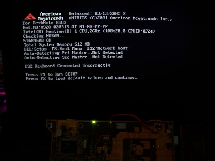
Crazy but what does that mean. That means when the panel idles and decides it wants to turn off, the back lights turn off as well. No button pushing or anything, completely automatic just like the original inverters. Preserving the original functionality. Another key test was soldering in the VGA wire that will eventually connect to the motherboard being used. First image is a test POST from the motherboard, just to ensure they talk to each other correctly.
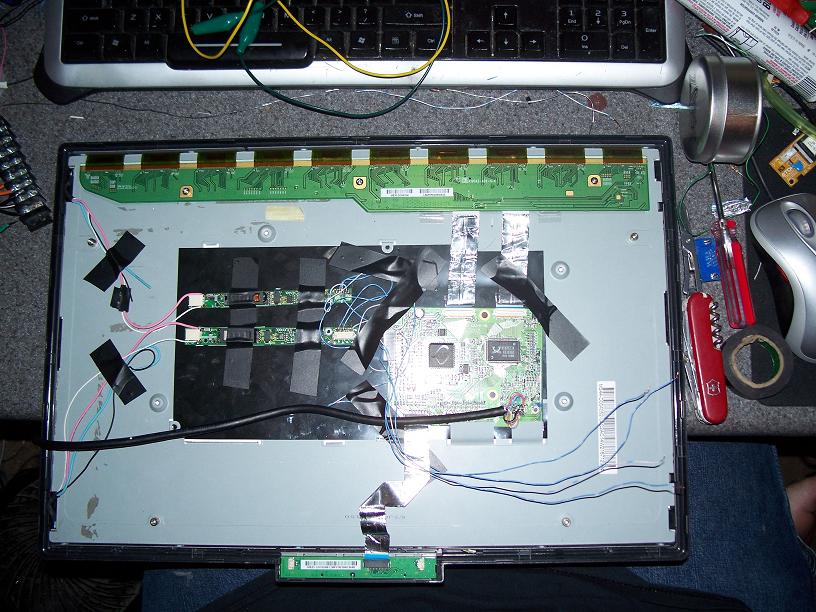
The image looks better in person, I’ve yet to master taking pictures of bright things like this. View of how the back looks so far, you can see the two laptop inverters being currently used. There is room to add two more to drive the other two cathodes in the display when I can find more compatible inverters. I have a whole box so chances are I already have them. Running 2/4 cathodes is perfectly bright, but by the end this project will be driving all 4 cathodes.
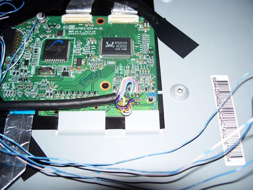
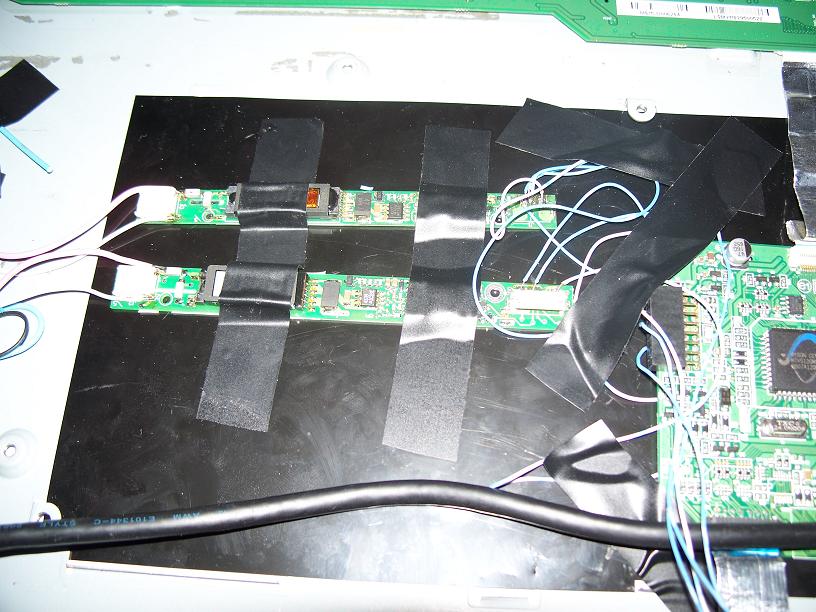
Close-up of where I soldered the VGA. It is worth noting here that I had originally used a thinner cable (originally a 9 wire serial cable). When that was hooked up the video crosstalk between the signals was too terrible to use. For this I just cut up my thinnest decent vga cable. Using the shielded R/G/B/sync really helps and now the video is crystal clear. I tested on a few sources. This project is about quality. Even though it is custom this computer should act and feel like the real thing. These are the laptop inverters. They had slightly different pinouts, this is to be expected with the thousands of laptops that exist. Still they each have a basic input of 5v and an enable line. If this is not the case do not bother with it.
Phase II
The LCD is now completely powered from various sources on the motherboard. This is also including the backlights. The entire computer is now able to boot and run under it’s own power, a single 20v input to the motherboard. So far just from general usage I have found the lcd to be a tad dim, this is to be completely expected when only driving 2/4 cathodes. Again by the end of this project all 4 will be powered, it is just a matter of me locating more compatible spare inverters. Though still completely usable from the tests I ran. I was able to watch a video and it seems to work great. The big goal here was to get the major electronics all assembled and working together for the first time. For this I went ahead and replaced the temporary wiring and I have created a connectible harness that goes between the LCD panel and the motherboard. This includes grounds, +5v, +20v, pwr_on, pwr_led. I have reused a 7812 voltage regulator from the original LCD PSU board. This is used to drive the 12v required by the logic on the LCD. Since I could not find a suitable source of 12v on the motherboard I decided to try the firewire jack. However that was a switched 20v supply because firewire makes no sense like that. The draw is so small from the LCD that using a small regulator like this was perfect. I have reused the heatsink just in case it needs any extra sinking.
I use a bit of electrical tape as you can see, everything is very well secure I can’t even wiggle it. And there is not really room for elaborate brackets to hold the inverters and other things. The backs of those were somewhat sticky and seem to stay in place perfect. The LCD driver board is kinda wedged with some metal and again taped in place well. I have rewired the front panel LCD controls so the green led is pwr_led from the computer and the main button is pwr_on from the computer. The menu button is now a power button for the LCD. The LCD from tests has always came on automatically when the computer starts supplying power to the LCD driver board. Just in case it needs to be cycles or fails to do that I have the function available. The auto config button has been wired up as normal to the LCD. Handy function to save navigating menus. The LCD has not been given a power LED. The whole thing is intended to be one unit so it would be redundant. Instead the extra orange LED has been wired to the LCD’s sleep LED supply so when the lcd is in standby the front panel led will be orange. Move your mouse to wake up the computer and it will all come right back on and the light will go green.
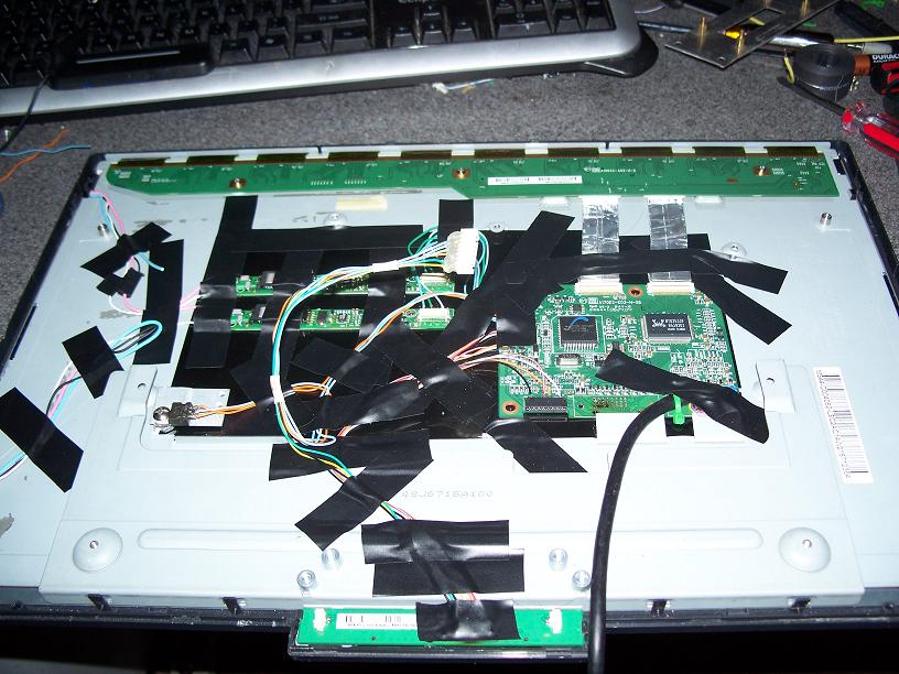
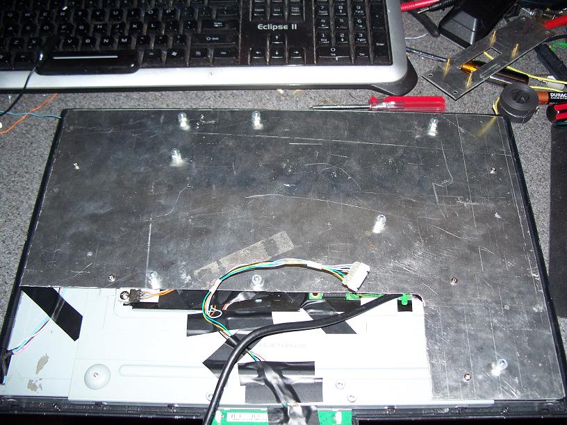
Here you can see all the connections on the back and everything taped down. Also there is the 7 pin connector to attach to the computer. I hot glued the solder joints to provide some ruggedness while testing and to ensure no stupid shorts happen. Here is the metal plate backing to cover the LCD electronics and provide a foundation for the motherboard to mount. You can see only the LCD 7pin cable and the VGA cable coming out from the front. A very clean setup.

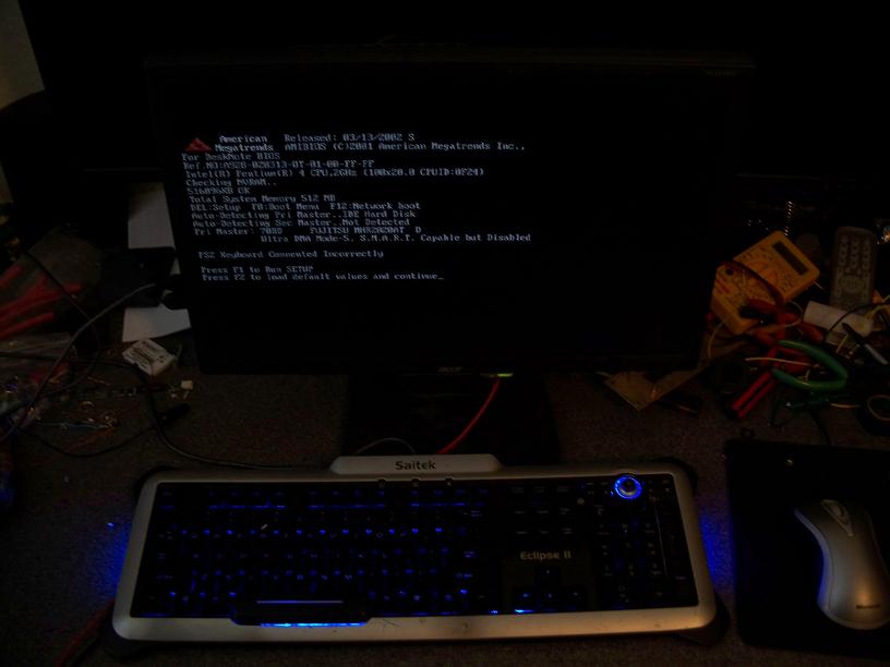
This is the mating end to the connection on the LCD. This is wired to all different parts of the board to get all the different signals and voltages for the LCD panel. Here is a shot of the whole unit setup in a test fashion and assembled like it will be when finished. As you can see it is just the panel a keyboard and a mouse.
Here is a short clip of the unit being turned on, going through the POST and then booting to an XP install. I have an 80gb HDD for this computer when it is finished and will get a brand new copy of XP so things run smoothly. As you can see in the video no the panel kicks on and everything starts up as it should. The power button of course controlling the computer.