Description
Introduction
These days virtually all new cars come with some sort of infotainment system generally controlled by the smartphone equivalent, the feature phone. The original radio in this car has given up the ghost many years ago and after installing several other headunits I decided it was time to finally install a Carputer.
Case
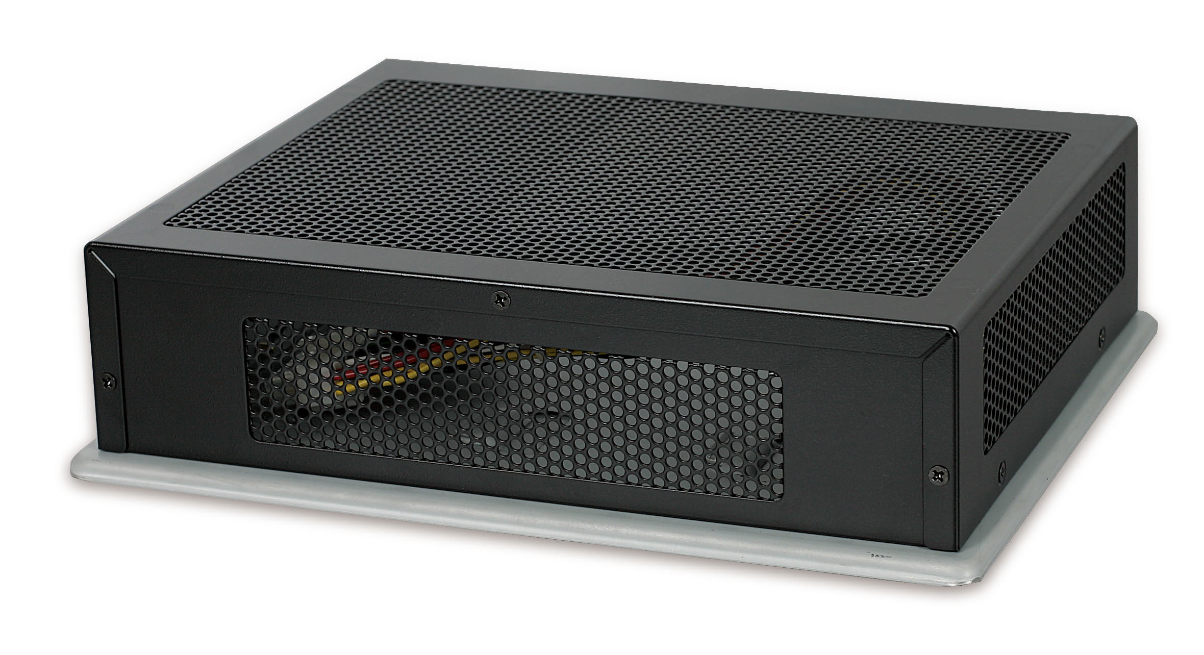
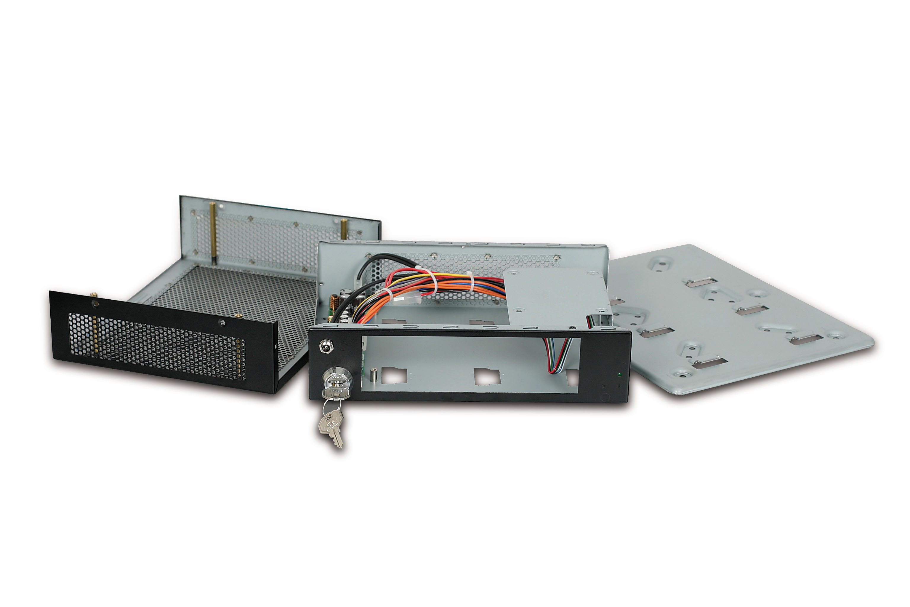
The Morex 5689 Mini-ITX case supports a form factor of 170mm x 170mm and is a superb choice with plenty of ventilation and an ultra strong mounting bracket secured with a key. The case comes with a DC-DC power supply however this is replaced with the M2-ATX as seen below.
Motherboard
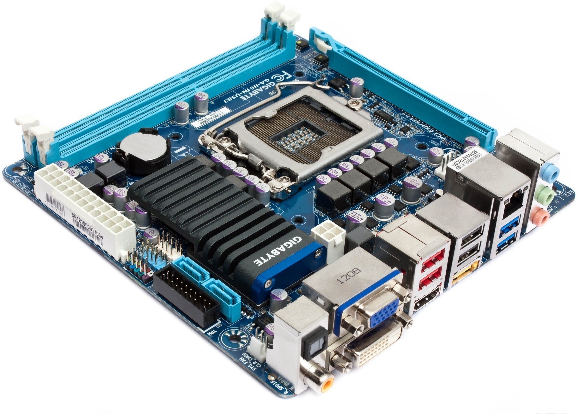
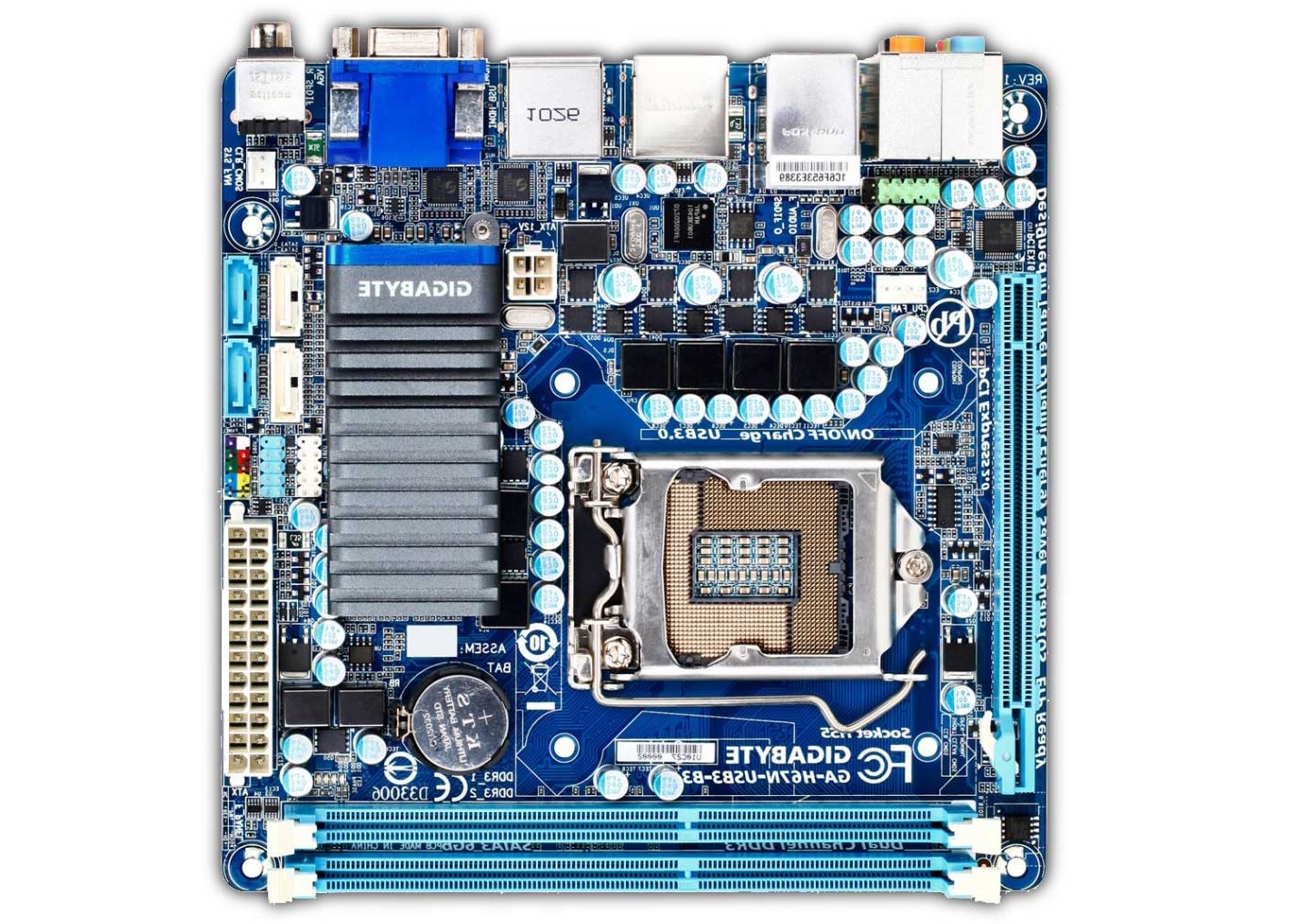
The Gigabyte GA-H61N-USB3 Mini-ITX motherboard has full desktop sized performance packed into one of the smallest possible form factors. Although I am not currently using the PCI-Express x16 slot one could use to connect a discreet graphics card. The onboard graphics available through the Intel Core-i3 processor are capable of playing games like Call of Duty Modern Warfare and Skyrim at near full settings. This will be plenty for running the front-end application Centrafuse with snappy animations and will allow videos to play smoothly.
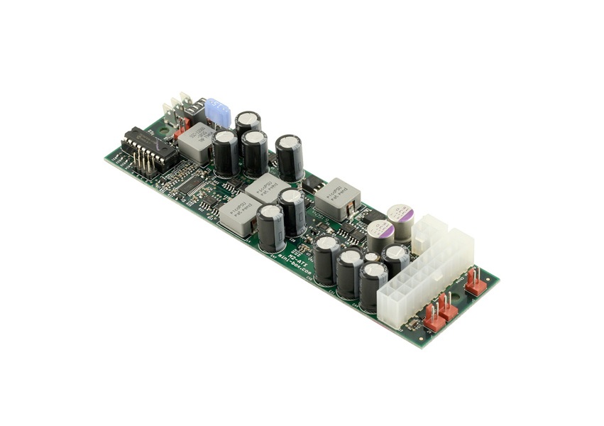
Power Supply
The Power Supply chosen here is known as the M2-ATX and delivers 160 Watts of output with a wide range input of 6 to 24 volts. This ensures that even during engine crank the computer won’t loose power and require it to reboot. The M2-ATX also features what is known as an intelligent shutdown controller that connects to the power switch connection on the motherboard. This lets the power supply signal for the computer to shutdown after a configurable amount of minutes. A hard shut-off time is also set in the event the computer fails to shut down on its own ensuring the car battery is never accidentally drained.

LCD and Touchscreen
The LCD and Touchscreen serve as the primary means of interacting with the computer. The Touchscreen is a resistive overlay placed on top of the physical LCD screen and connects to the computer over USB. The Touchscreen can continue to function even if the LCD itself is switched off since the control boards for the Touchscreen and LCD are separate.
Fabricating frame and mounting
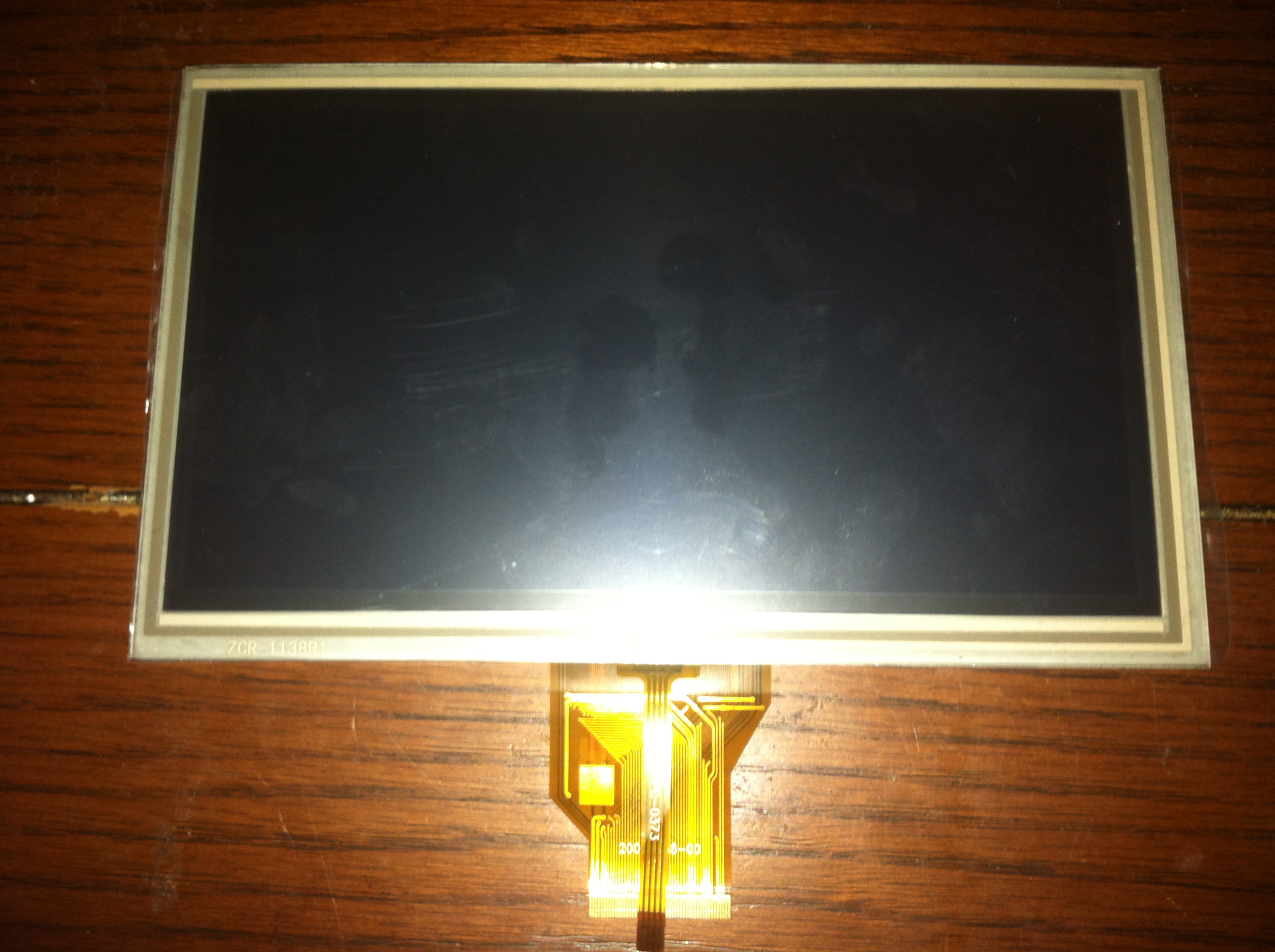

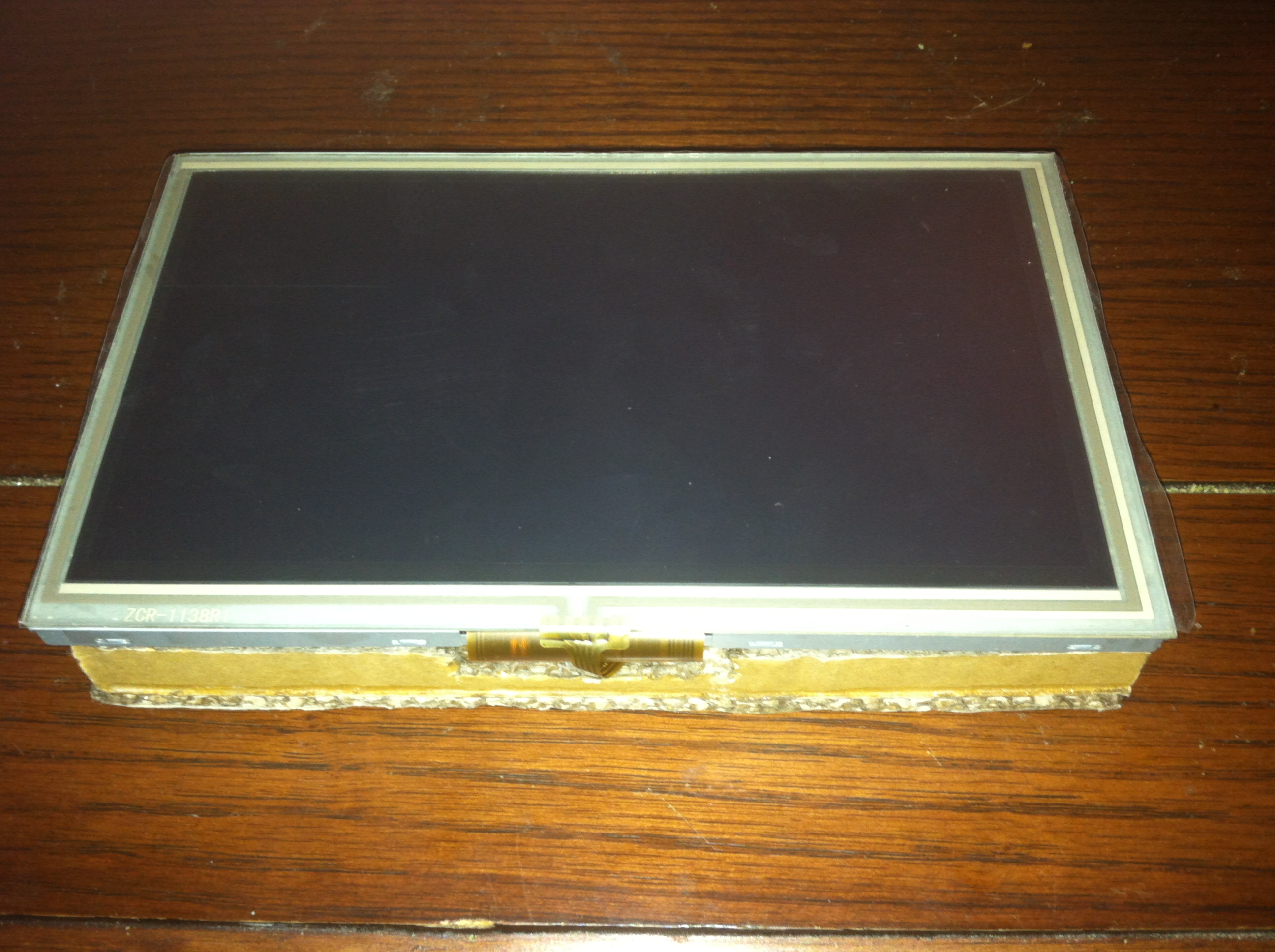
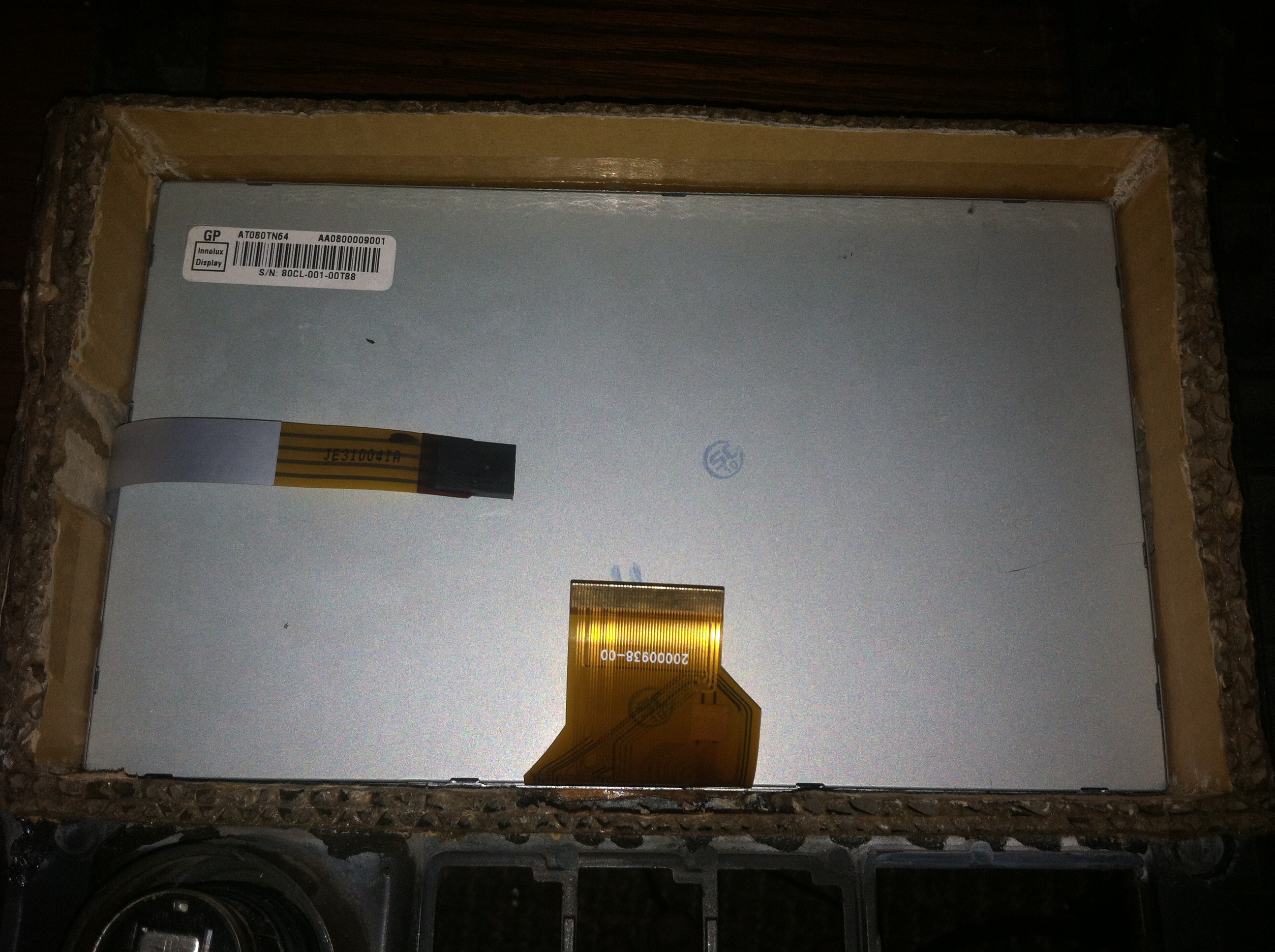
Meet the LCD and Touchscreen, these come as a barebones solution that is just waiting to be integrated into your own project. The display has a native resolution of 800×480 pixels and can downscale all the way from 1920×1080. The reason why this is a great feature isn’t apparent until you see the picture in real life. Using a technology built into the controller the display will read in-between the available pixels and combine pixels where possible into smaller sub pixels.
eBay Search “AT080TN64 HDMI” – Search just the part number to find many other driver boards compatible with the display.
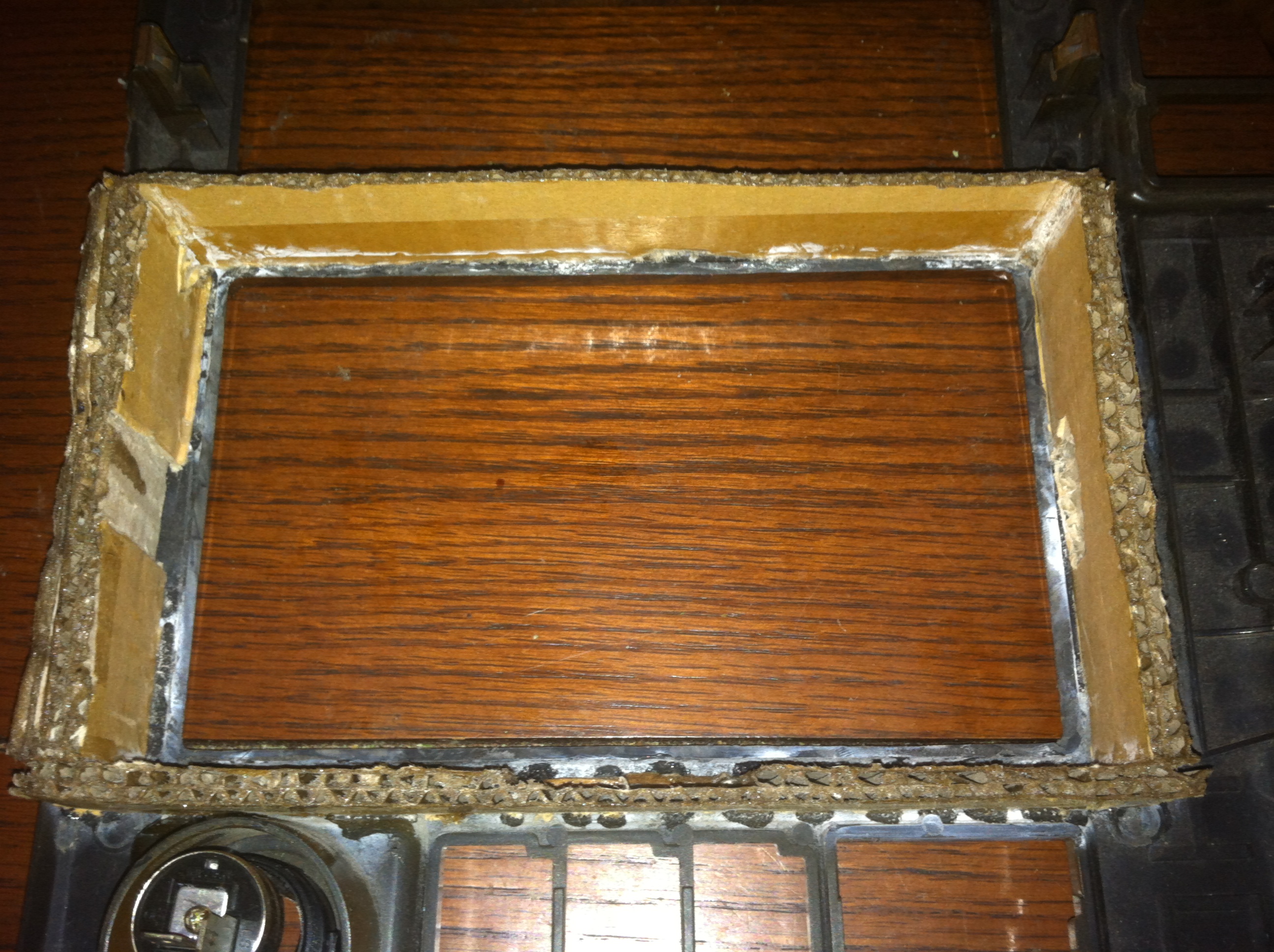
First a frame was constructed using cardboard, yes, cardboard. Using industrial strength epoxy and super glue to attach pieces and on all the exposed edges creates an incredibly strong structure that is easy to work with. The frame is then attached to the rear side of the dash panel from my car with care taken to ensure the optimal placement of the screen in the opening of the dash. Next a backplate is created that will pressure fit the display to the back of the dash creating as tight of a seal as possible with the lip of the dash and the front of the display.
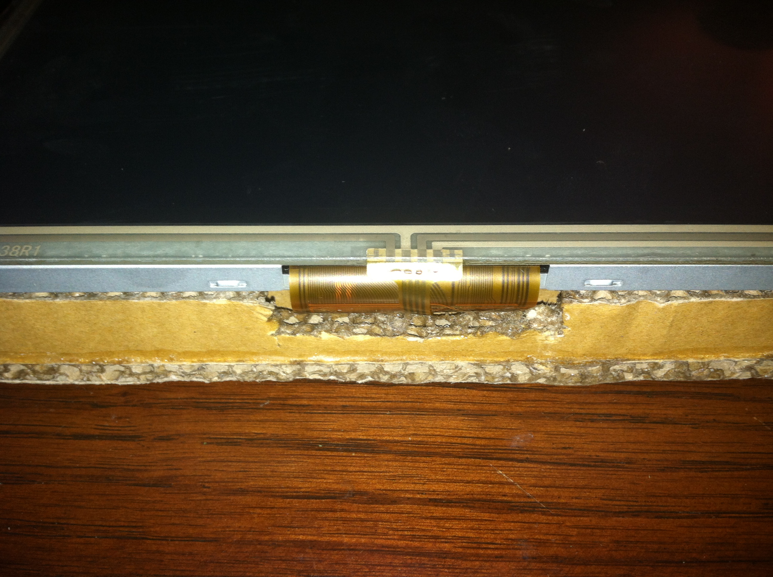
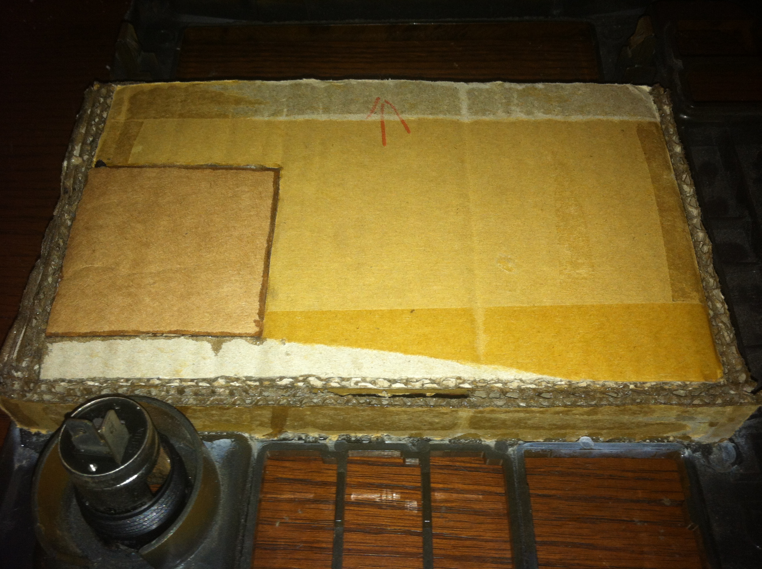
The backplane will need several cuts made to accommodate the ports on the controller board as well as the data ribbon for the LCD panel. This is cut out here and a small notch created on the inside frame (not pictured) so that the data cable will flex as needed not become crimped or damaged.
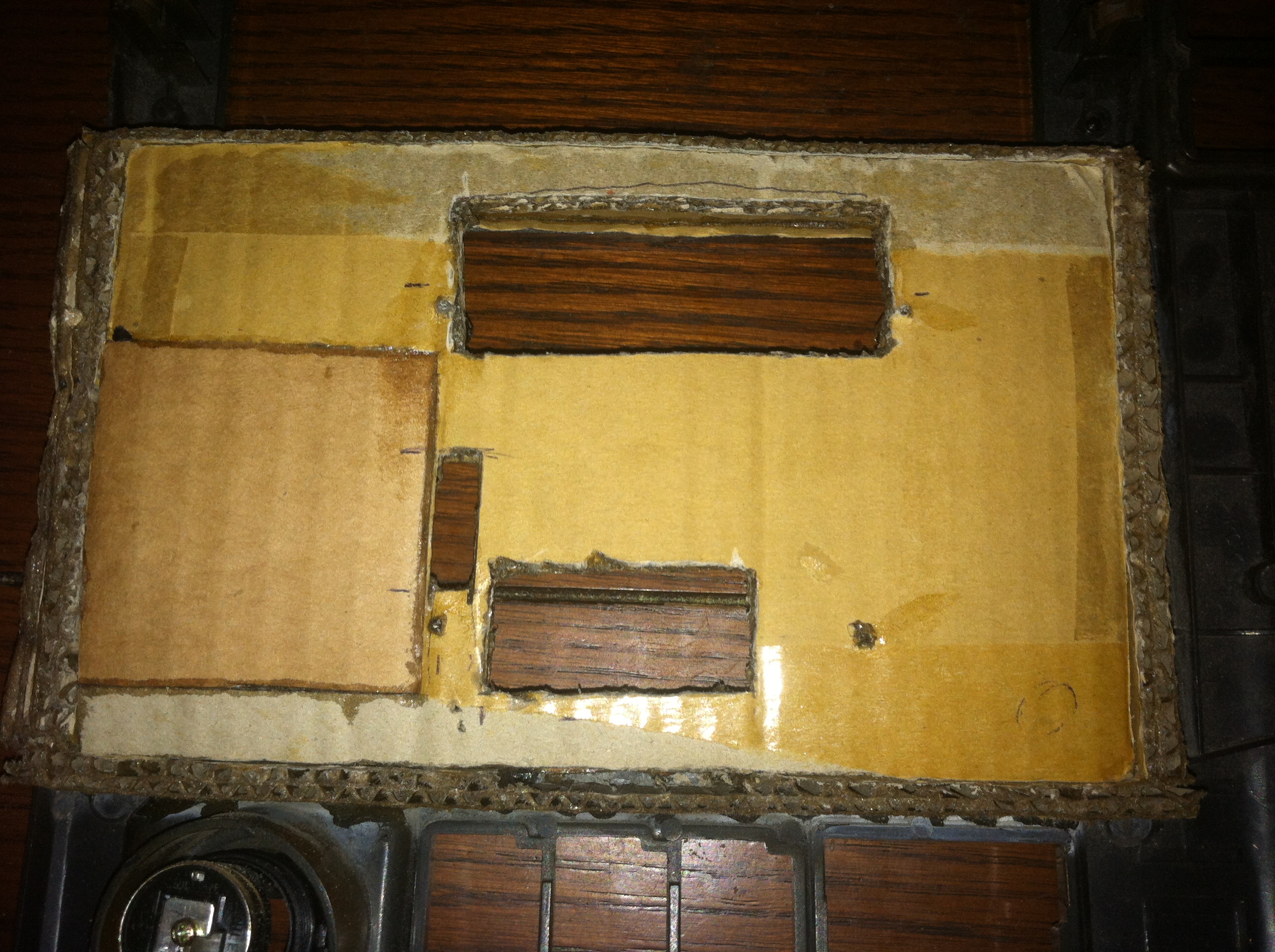
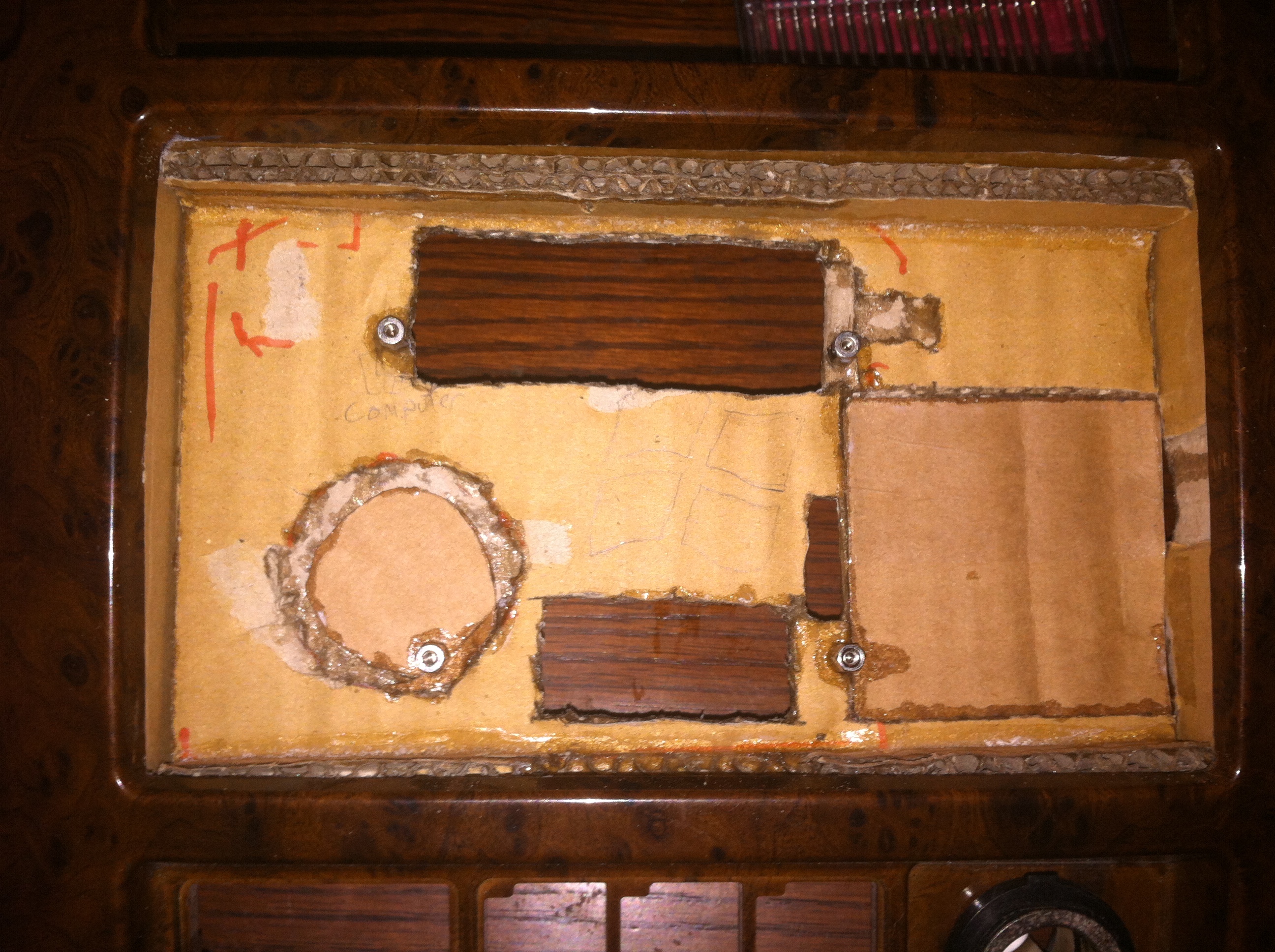
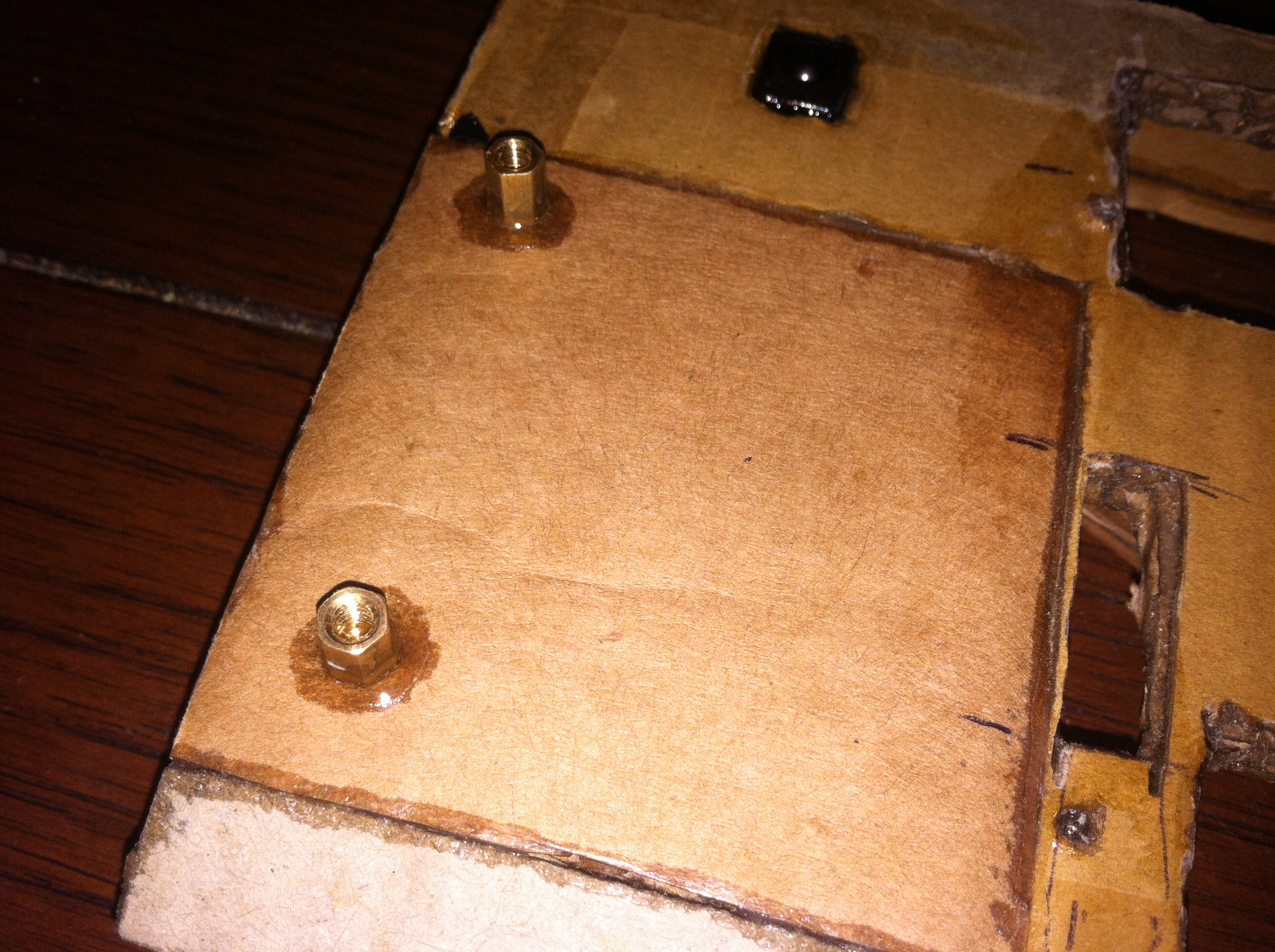
Holes are cut out of the backplane for access to the main connectors, the LCD data connector, and the button board connector. They are sealed up with more epoxy, this has the effect of making the backplane even more rigid. Standoffs are then placed and bolted to the cardboard, this is accomplished by drilling a hole in cardboard then placing a small tab of epoxy such that the edges soak up the glue but the hole is not filled in. After waiting a few minutes drop slightly more glue in and start screwing in the standoff, more glue is then placed around the edges creating a surprisingly strong mount point. With four total standoffs for the driver board I can be sure it will stay put.
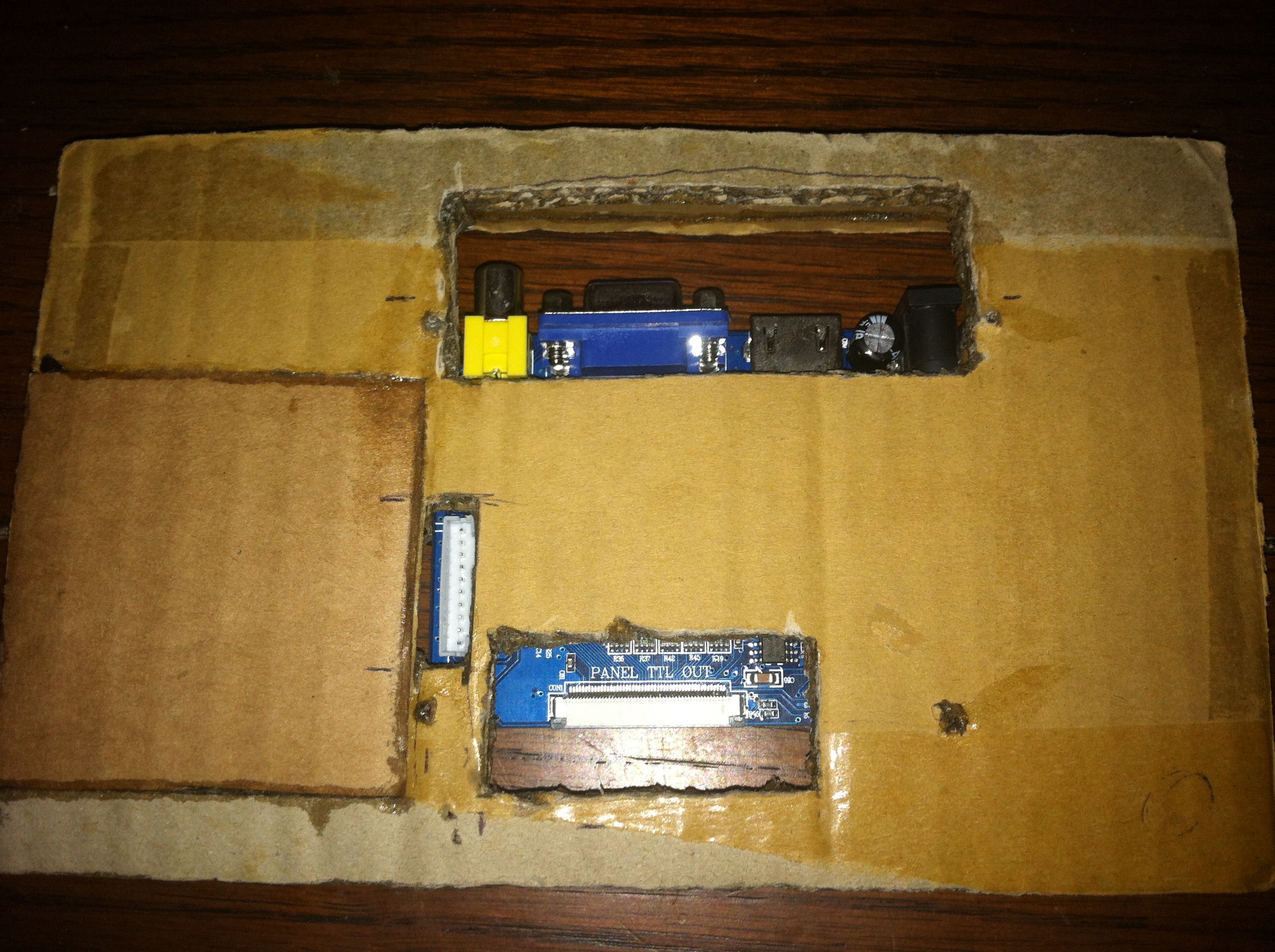
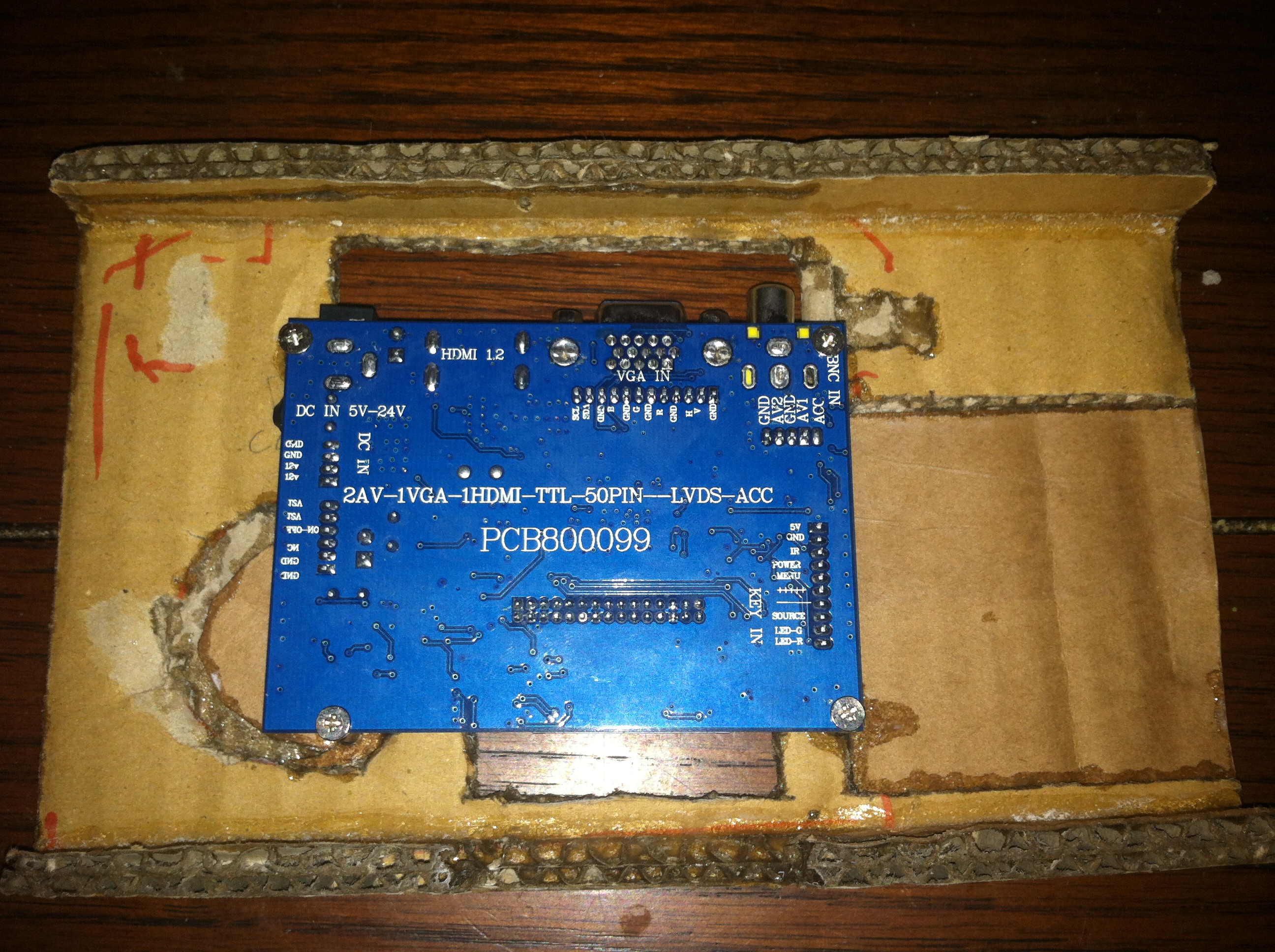
This shows the control board mounted to the backplane and showing the visibility of the connectors as seen from the rear of the backplane. This is a great time to comment on all the extra cuts on the backplane that don’t correspond to the layout of components. The original install of this system used a display (Lilliput screen noted below) that is identical in dimensions and picture to my new display.

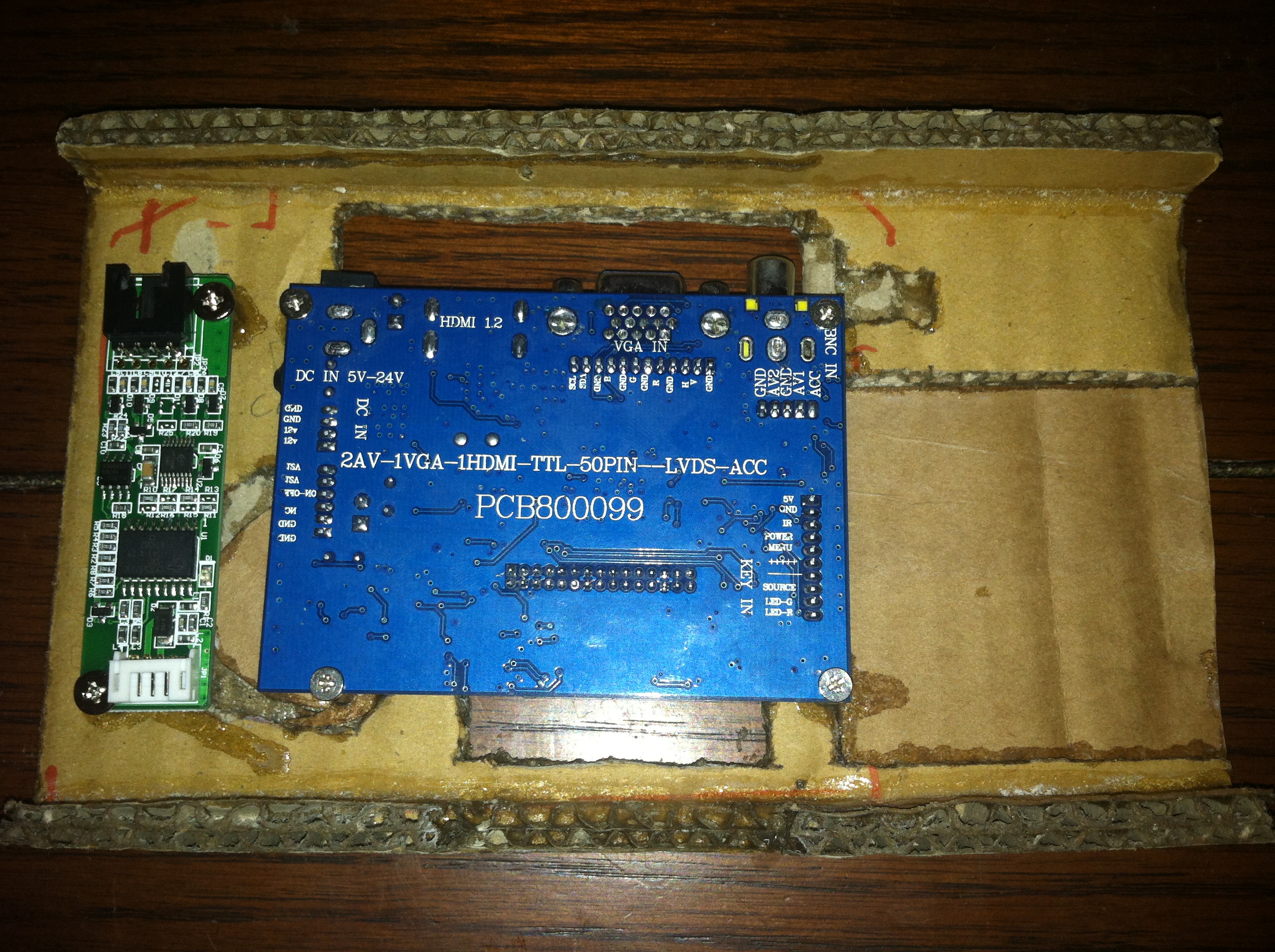
The Touchscreen controller is then mounted in some free space next to the control board. This connects to the Touchscreen overlay that is mounted just in front of the display, this one is resistive but it has a special transflective coating that reduces glare from sunlight. The same process described above for the control board standoffs is used here to mount the Touchscreen controller.
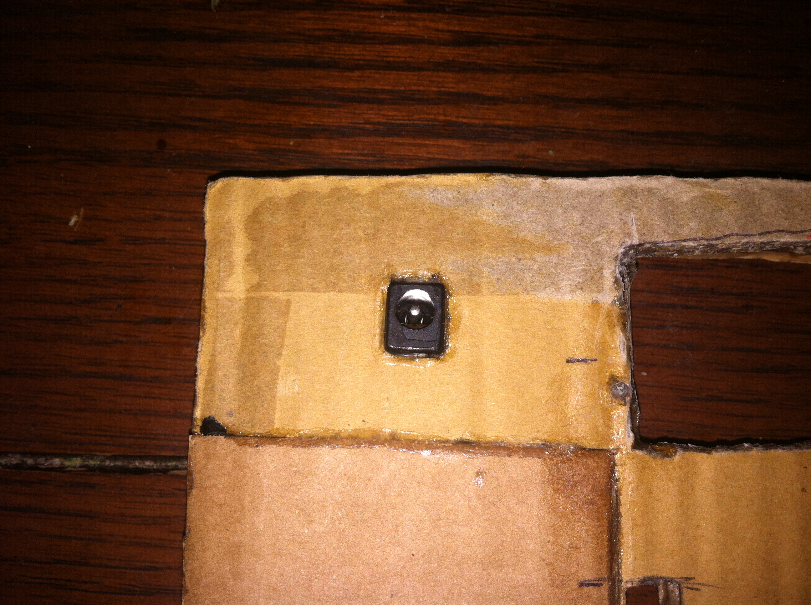

Realistically speaking unless your cable is a right or left angle depending on the respective port’s orientation you won’t be able to plug anything into the control board. A right angle (270 degree) HDMI pass through was ordered for the tougher connector but the power connector was easy to simply duplicate elsewhere on the backplane. The control board features a connector that allows an external power source to be connected, in this case a barrel jack is secured to the backplane and connected to the control board.
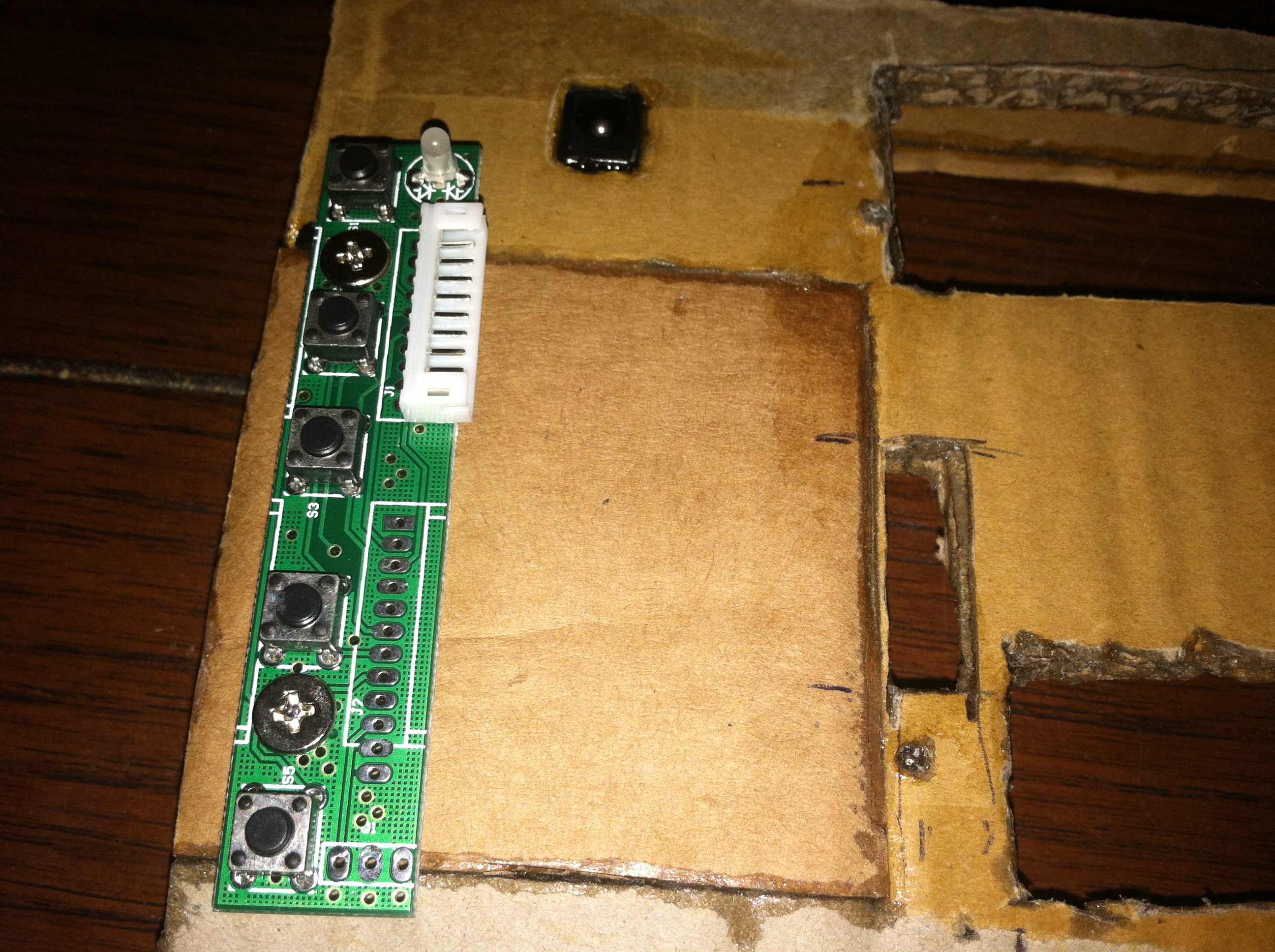
The button board isn’t a requirement for the display to function however its an easy addition that will help setup the display and will later be hidden once installed in the car. I can then solder additional connections to the button board to tap into the LED and buttons if needed without modifying the more expensive control board.

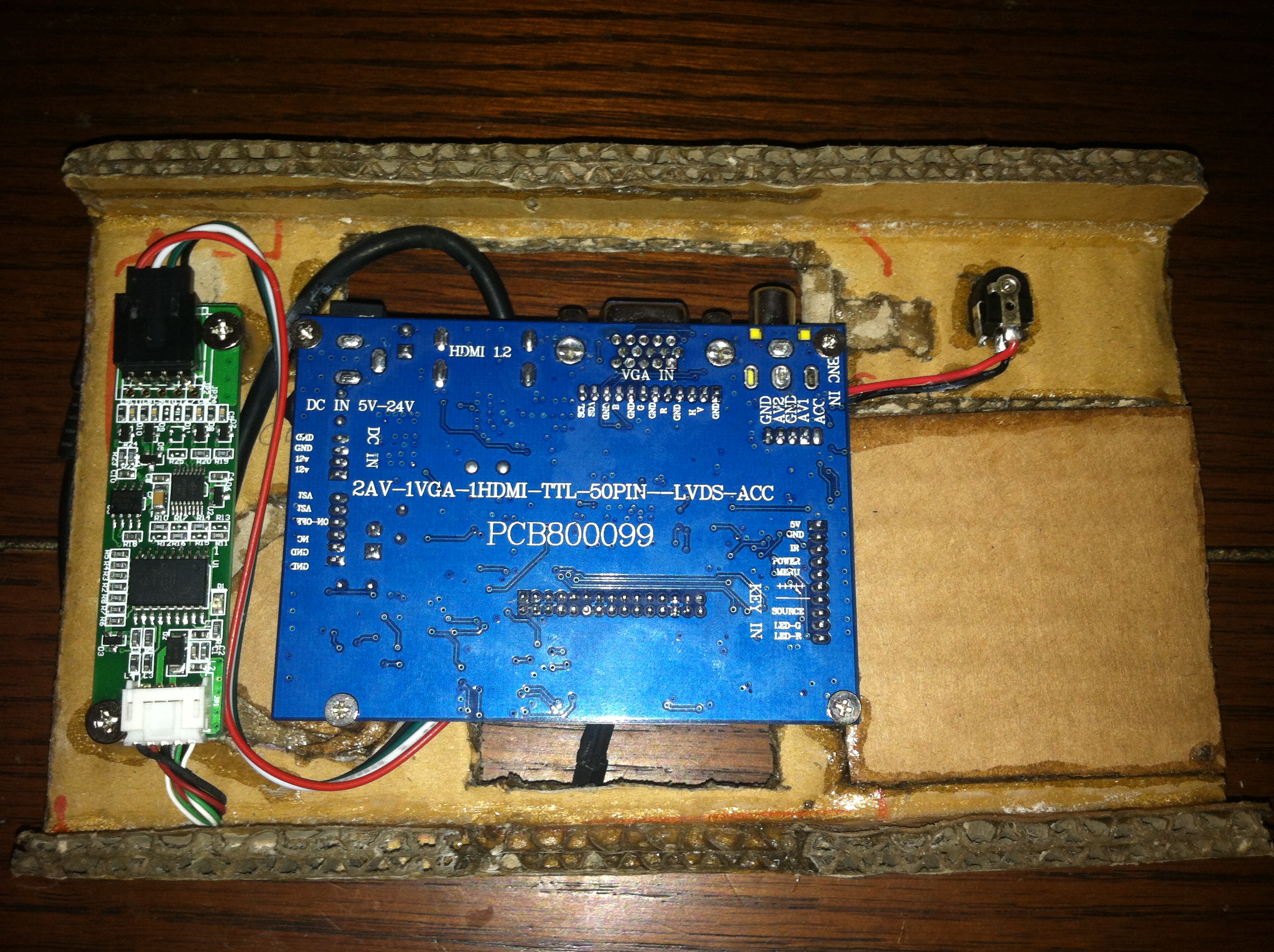
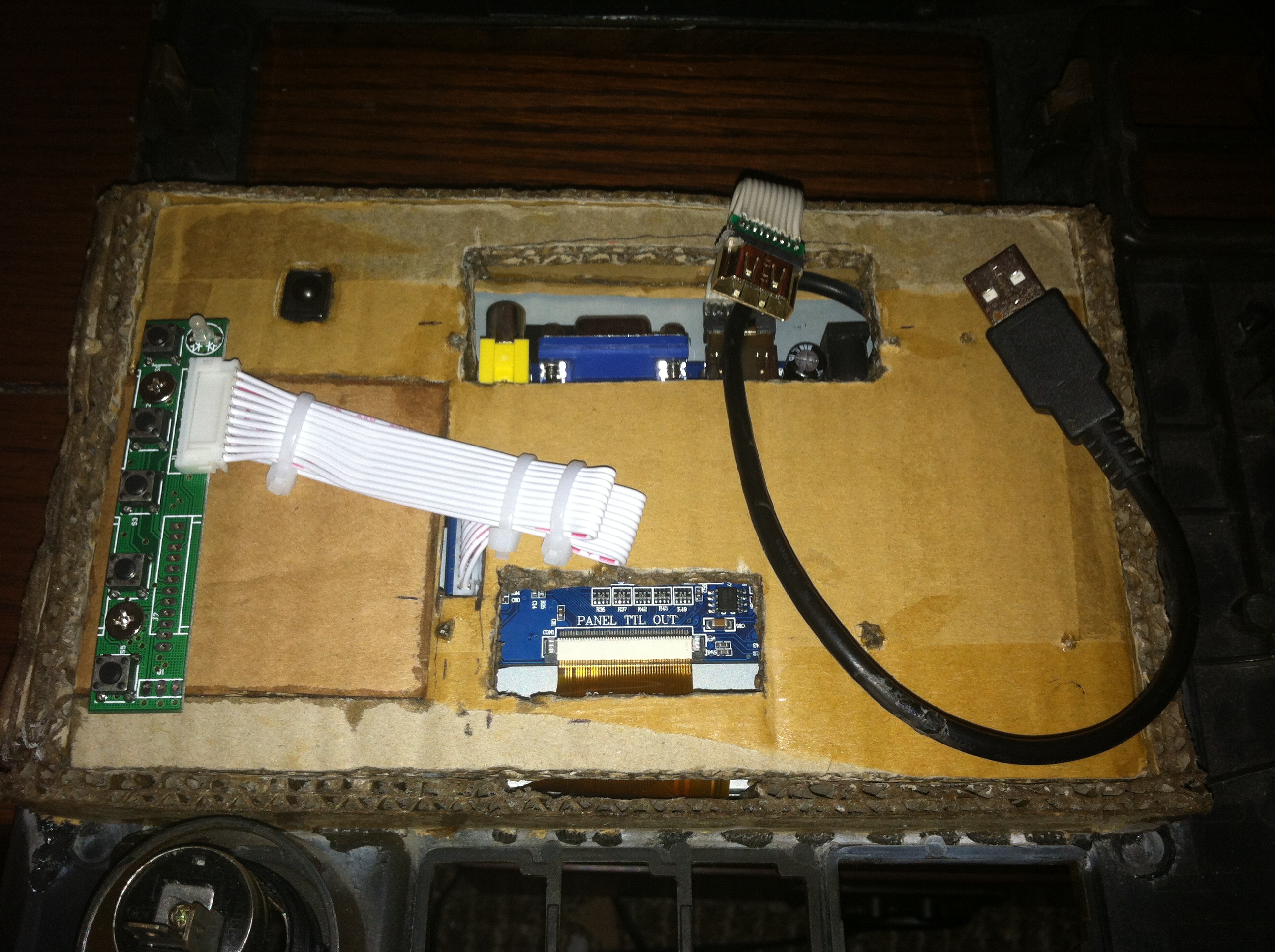
Wrapping up this phase of the project we can see the completed assembly of components on the backplane. The USB cable connects to the Touchscreen control board and the white ribbon is a fairly long cable folded around and connected between the button board and the control board.
Final Assembly
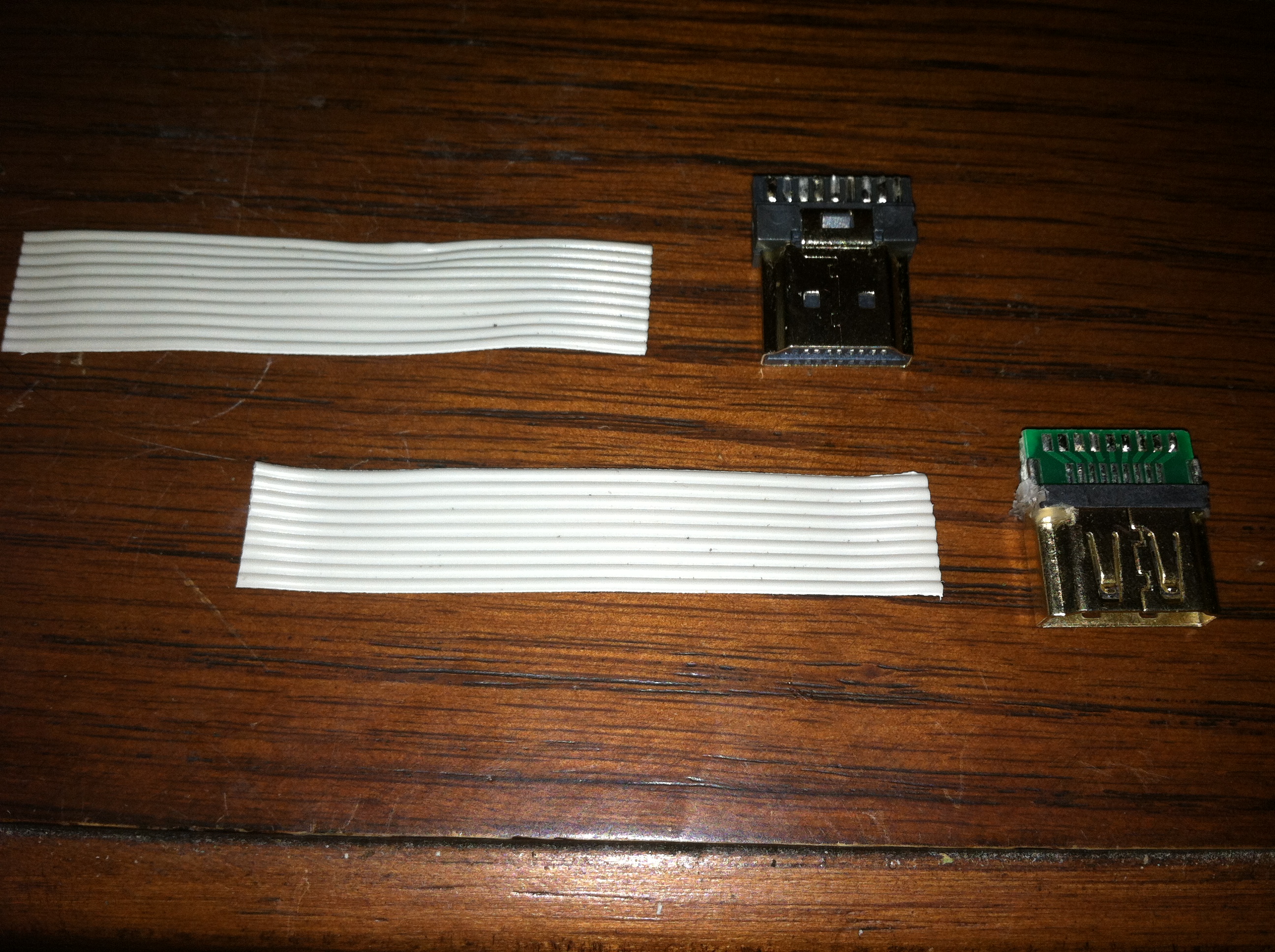
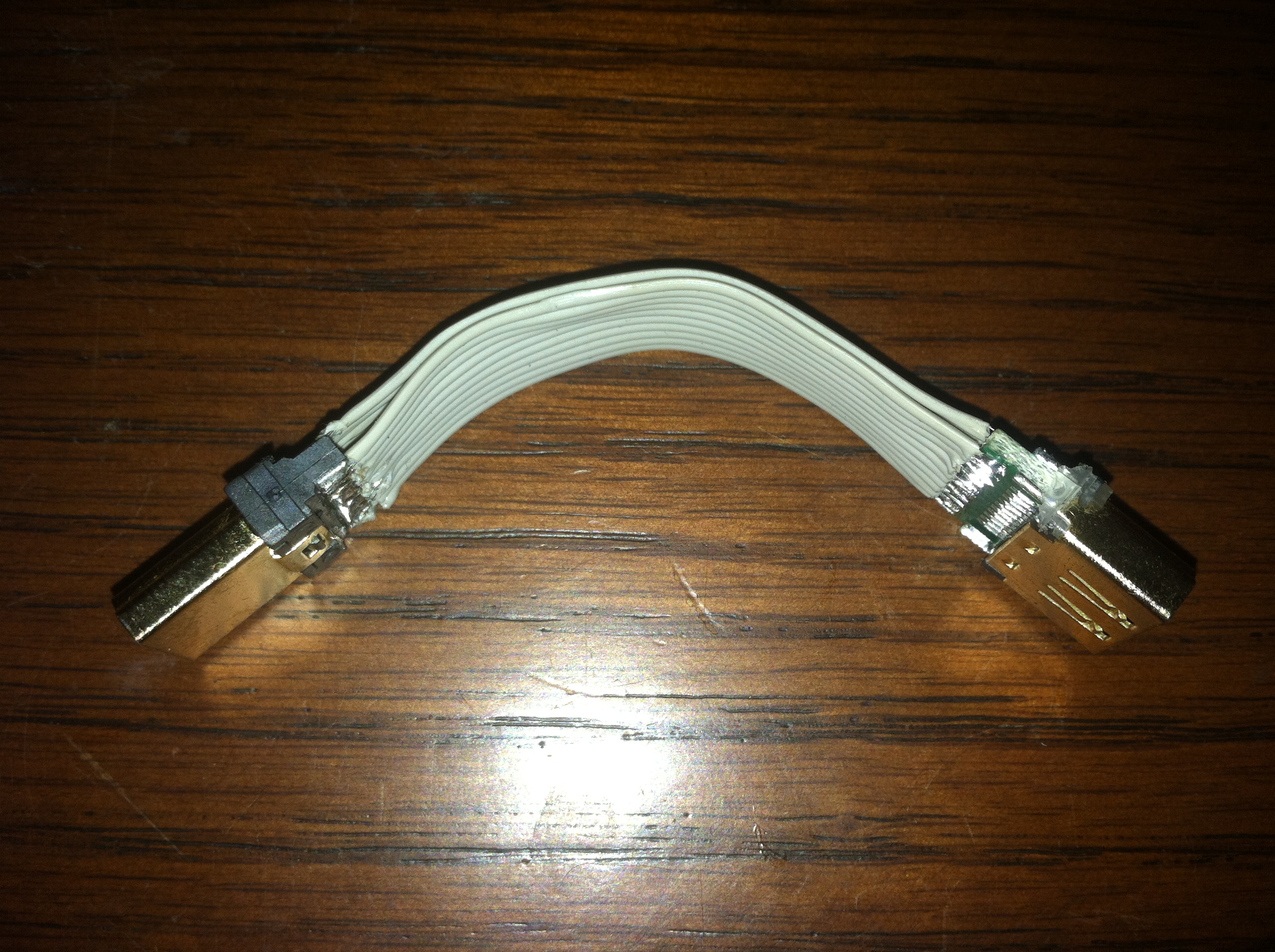
I ordered a right angle HDMI connector for this project however at the time of writing this portion of the project log I have not yet received it. Being impatient I dug around in my parts bin and found both male and female HDMI plugs and put together a simple 4” HDMI extension. I will probably replace this with the right angle adapter when and if it comes in the mail.
Next the LCD panel is fitted into the frame and the backplane is fitted next connecting the LCD data cable and the Touchscreen data cable. The backplane is secured by 4 small dabs of epoxy (not pictured) that will ensure the backplane stays in place for even the most ferocious of finger presses. I can easily cut through these with a utility knife or the blade on my Dremel should I need to access th LCD assembly again.
Initial Installation
There were only a few pictures taken of the work going into the original installation mostly due to the high-risk nature of many phases possibly not working out. There are many aspects of this project such as the mounting of the display that I was very unsure about but turned out great in the end.
Base Hardware Install
These are the first shots of the system up and running and before I had settled on the final front end software, Centrafuse, detailed more in the software sections.

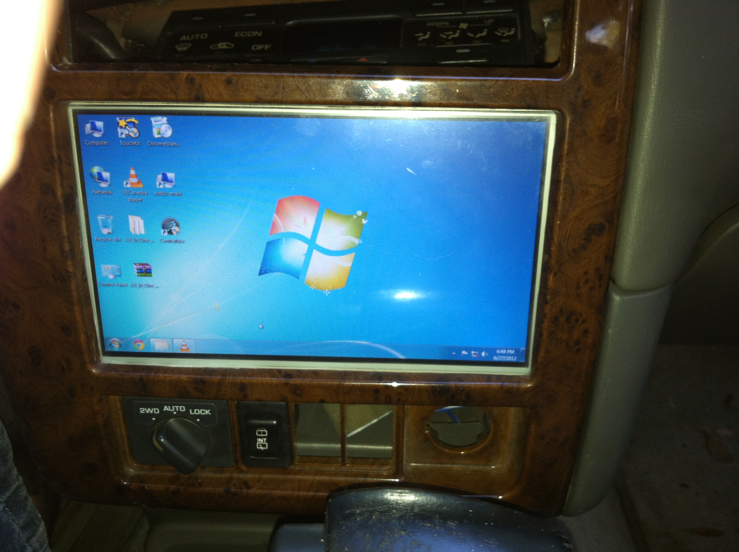
One of the greatest features about the computer is that when you get fed up with the front-end software or just need access to something more powerful the underlying operating system Windows 7 is just a few clicks away. This makes managing devices such as your external media drives, wifi adapters, bluetooth connections, access to a full on web browser, games like call of duty, and emulators for systems like the N64.
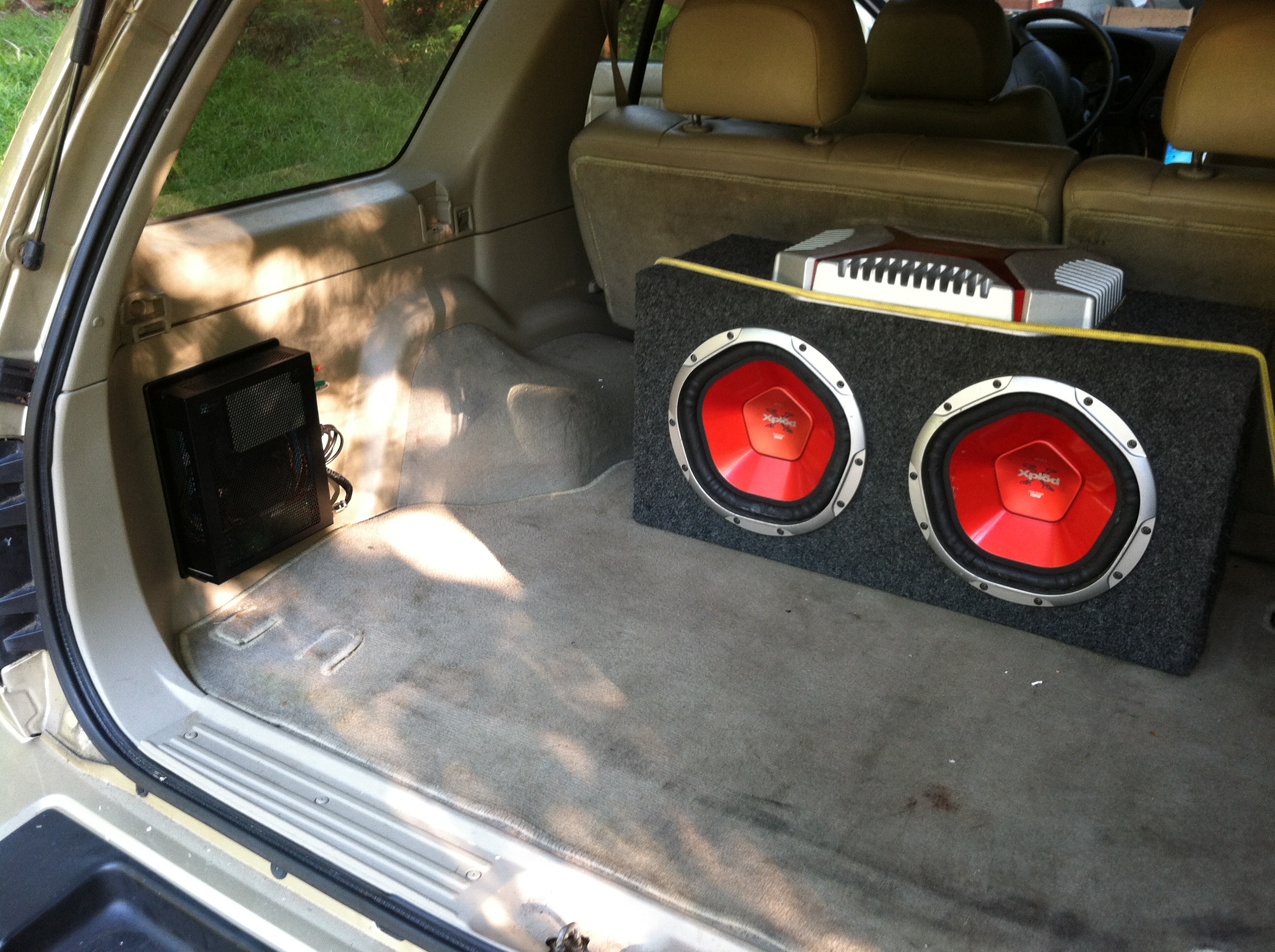
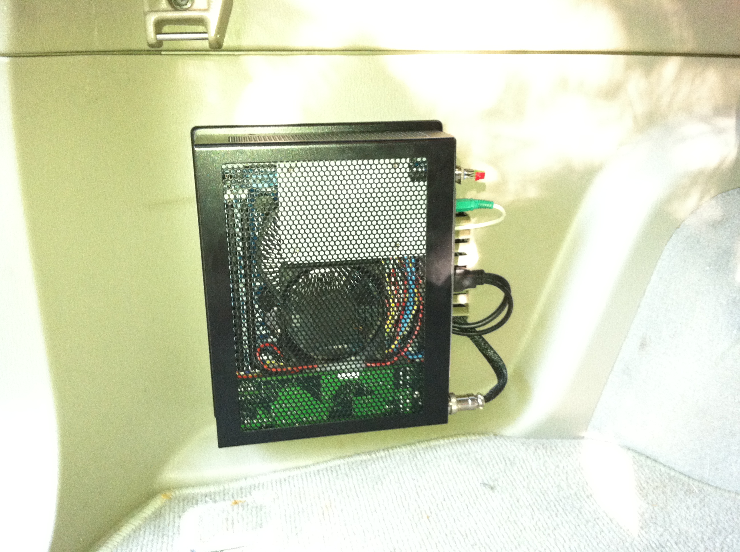
I have installed the computer using its mounting plate on a panel on the drivers side of the vehicle. The computer locks with a key and easily allows me to take the unit out of the vehicle if I need to take it inside to work on or upgrade the computer. There was a small vent where I mounted the plate so I routed the cables that connect the computer to the various peripherals in the car. This means if I choose to completely remove the computer system that there will only be 4 relatively small holes in the panel where the plate was mounted. Using screw hole inserts (common in the automotive industry) I can cover the holes completely removing any obvious evidence there was ever something installed. Panels like this one often come with holes drilled and fitted with caps where accessories can be mounted in the future.
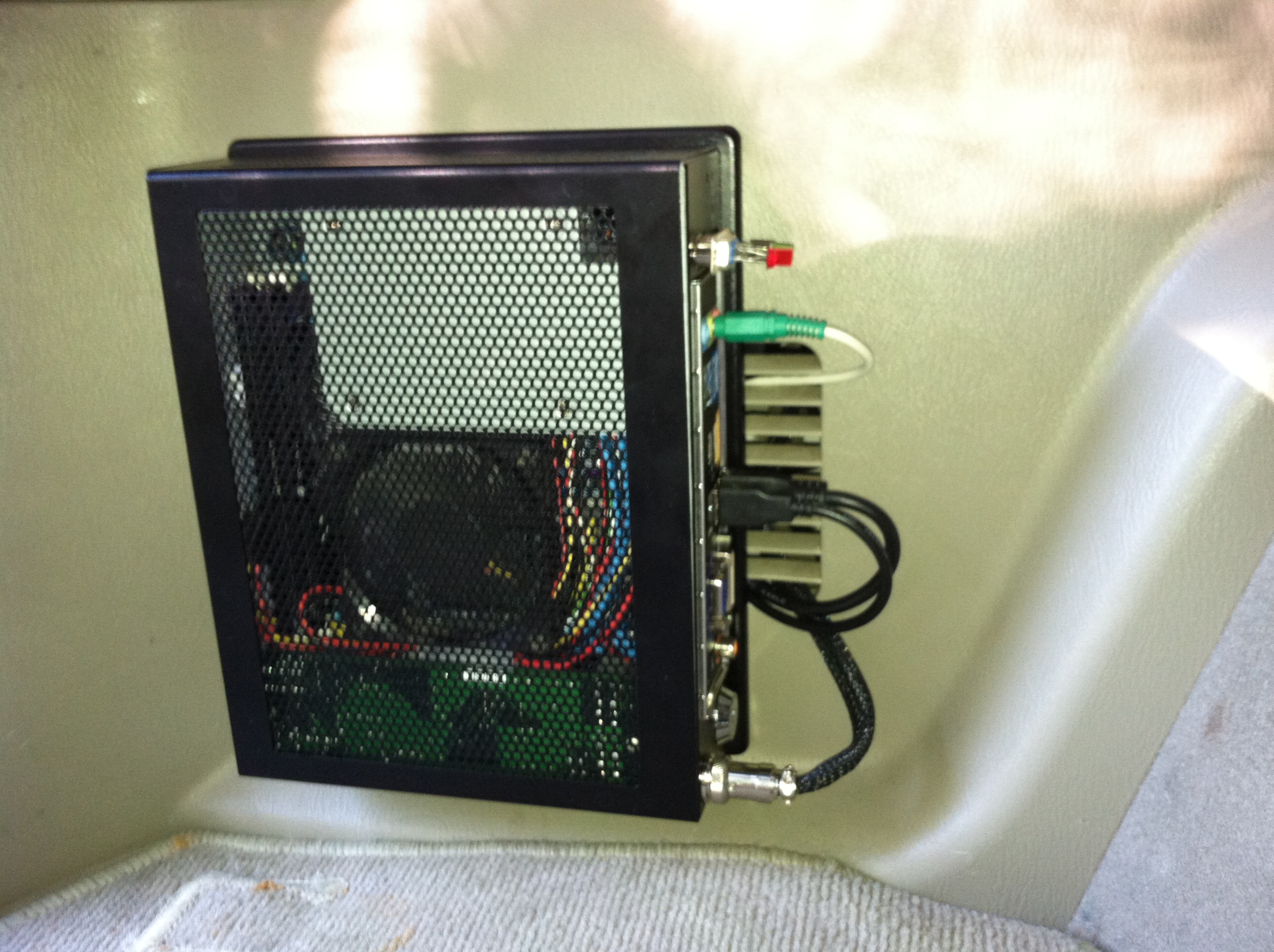
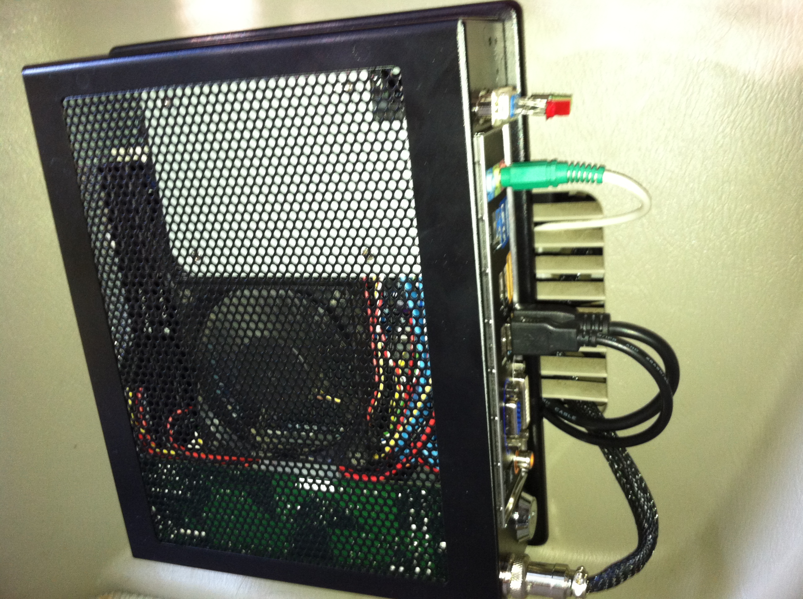
This shows the absolute minimum of connections necessary to connect the LCD, Touchscreen, External HDD, Audio, and Power. I added a DB-9 port on the rear of the computer which acts as a remote front panel connection. This is detailed above and with the use of a 15 foot DB-9 extension I am able to connect a power button and LED’s for power and HDD activity in the front of the vehicle. This could have been achieved in other ways but I’m a sucker for modular connectors and I have used this same connection on other projects such as Media-PC Reborn.
Software and Front End


The software I have chosen as a front-end for the computer is called Centrafuse, they claim they also license their platform to manufacturers of integrated systems though they don’t list which ones likely due to licensing agreements. Detailed more in the above updated software section the front-end allows easy access to the entire media library (about 900GB) with large buttons and text. After just a week of using the front-end I can already navigate most items without looking at the display at all. Buttons are generally kept in the same locations regardless of the screen you are on creating a consistent user experience reducing the risk of distraction while driving. I don’t condone the usage of these systems when there is any risk of injuring yourself or others, please operate them safely.
Parts and Cost
Breakdown
Below I have listed nearly all the parts used in this project. Any additional equipment used were items that came out of my parts bin and/or tools like needing a soldering iron and then using quite a bit of solder.
- Intel Core i3-2105 Sandy Bridge 3.1GHz HD Graphics 3000
- Western Digital Scorpio Blue 1TB SATA 3.0Gb/s
- 8 inch 800*480 AT080TN64 LCD + HDMI+VGA+2AV Controller + Touchscreen and Controller
- GIGABYTE GA-H61N-USB3 LGA 1155 Mini ITX Motherboard
- M2-ATX 160w 6v to 24v Intelligent Automotive DC-DC Car PC Power Supply
- Morex 5689 Locking Mini-ITX Case
- OCZ Onyx Series 2.5″ 32GB SATA II MLC SSD
- CORSAIR XMS3 8GB (2 x 4GB) 240-Pin DDR3 1333mhz (PC3 10600)
- Vantec NexStar 2.5″ SATA to USB 3.0 Enclosure
- 15 foot USB 3.0 Extension Cable Male to Female
- 15 foot HDMI Extension Cable Male to Female
Justification
This is best summed up by the Introduction to this project and really all comes down to personal preference. There are a lot of people though who will be content with the stock headunit (radio/cd player/etc) or just want an audio input. Having the ability to access my entire Music library using a convenient interface. As detailed in the Software section I also have a sizable Media library part of which I am able to fit on the 1 TB removable HDD. Tying in WiFi or USB tethering with my smartphone and I am able to use services like YouTube, Pandora, Spotify, or anything else that requires internet.
Final Thoughts
HDMI vs VGA Connection
The difference is night and day, interference is virtually non existent with absolutely zero image ghosting. Generally you should expect to pay around $10 to $20 more for a display that is compatible with HDMI. The cables are just as cheap or cheaper and support resolutions of 1920×1080 or higher from one end of your car to the other. The display I used has both HDMI and VGA connections and could allow you to slowly upgrade your install or to use the additional input for another device that outputs HDMI or VGA.
External Hard Drive
I would like to find a refined method of connecting the external hard drive to the computer. I have the drive in the front of the car connected to the 15 foot USB 3.0 cable. This works although I do have to supply additional power which is not unexpected it’s just another gotcha. The drive doesn’t enumerate as quickie as other devices which I suspect is an issue with Windows 7 not natively supporting the USB 3.0 controller and having to wait for the drivers to load.