Hardware Setup
An important factor with the decisions on hardware has been to get the minimum possible host hardware to support the graphics cards. Since mining on a CPU is impractical we have chosen the cheapest available motherboard with 5 PCI-Express slots (of any type x1 – x16) and configured with the least expensive CPU possible.
Test Setup and Software Configuration
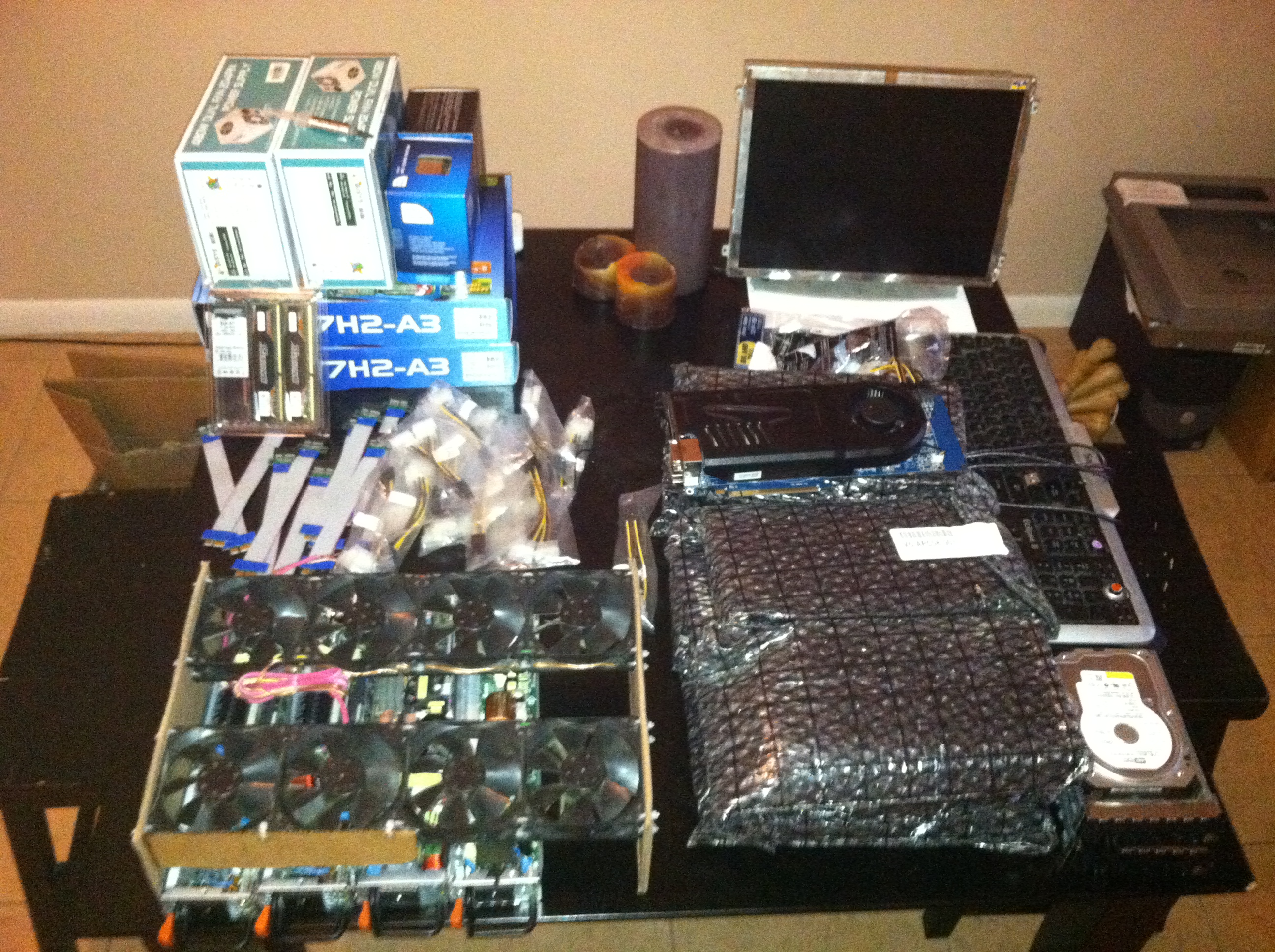
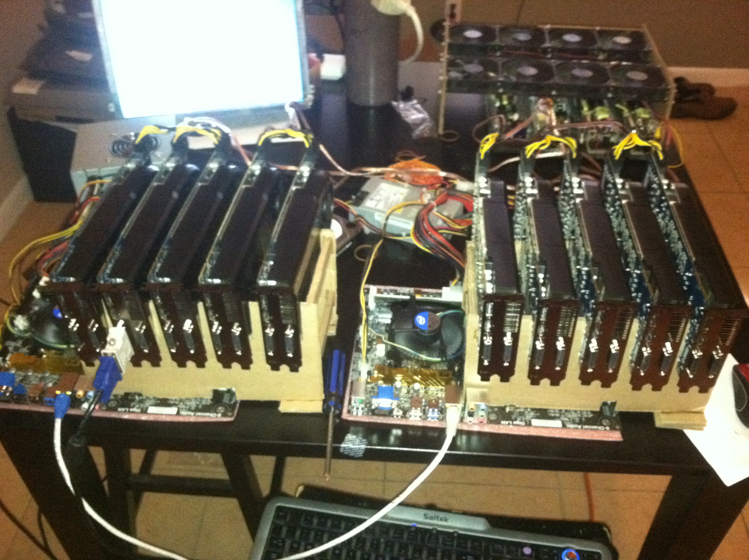
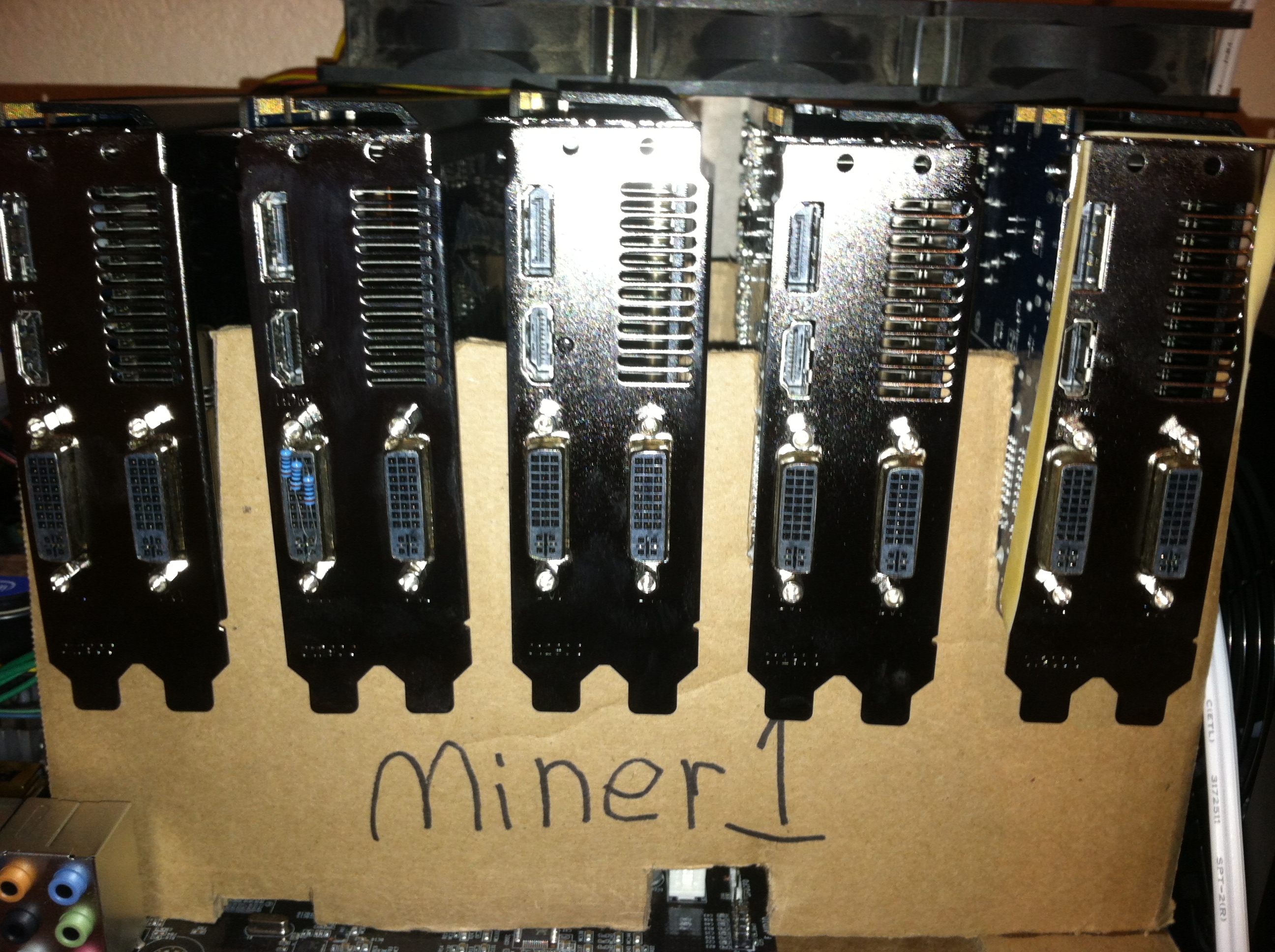
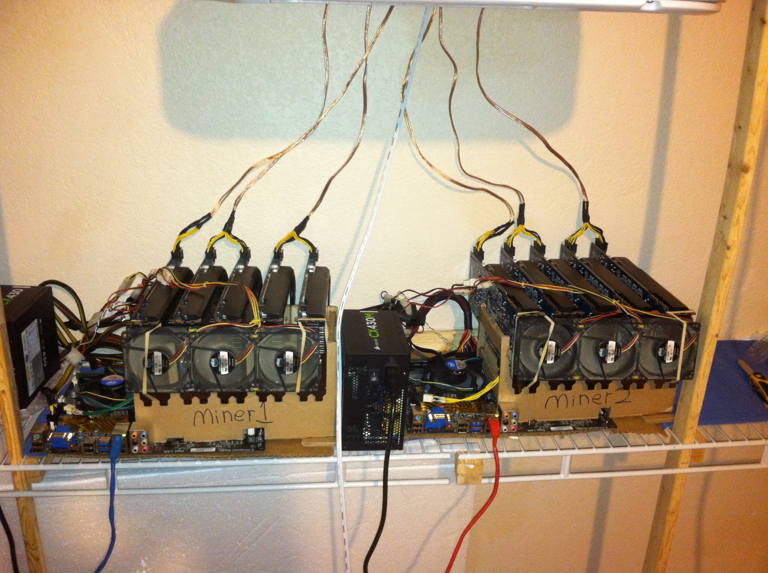
The best part of any build is getting to unbox lots of new hardware. First a pair of holders were constructed out of commercial grade cardboard to suspend the graphics cards above the motherboard with spacing for airflow and the PCI-Express risers that connect the cards to the various slots on the motherboard. Windows 7 is chosen as the operating system using guiminer for mining.
- 2x ECS X77H2-A3 LGA 1155 Intel H77 ATX Motherboard
- 2x Intel Celeron Ivy Bridge 2.6GHz LGA 1155 55W Dual-Core Processor
- 1x Crucial Ballistix Sport 8GB (2 x 4GB) 240-Pin DDR3 1333
- 2x CORSAIR CX430M 430W Modular Active PFC Power Supply
Cheapskates VGA Dummy Plug
Although the drivers for ATI cards on both Windows and Linux are getting better about allowing the graphics card to run even when there is no monitor attached it is still necessary in Windows to attach a monitor or what is known as a dummy plug or dummy load to trick the computer into thinking a monitor is attached. Below a simple dummy plug is created by connecting 3 resistors to the Red, Green, and Blue connections on the DVI plug for VGA compatibility and grounding the other side.
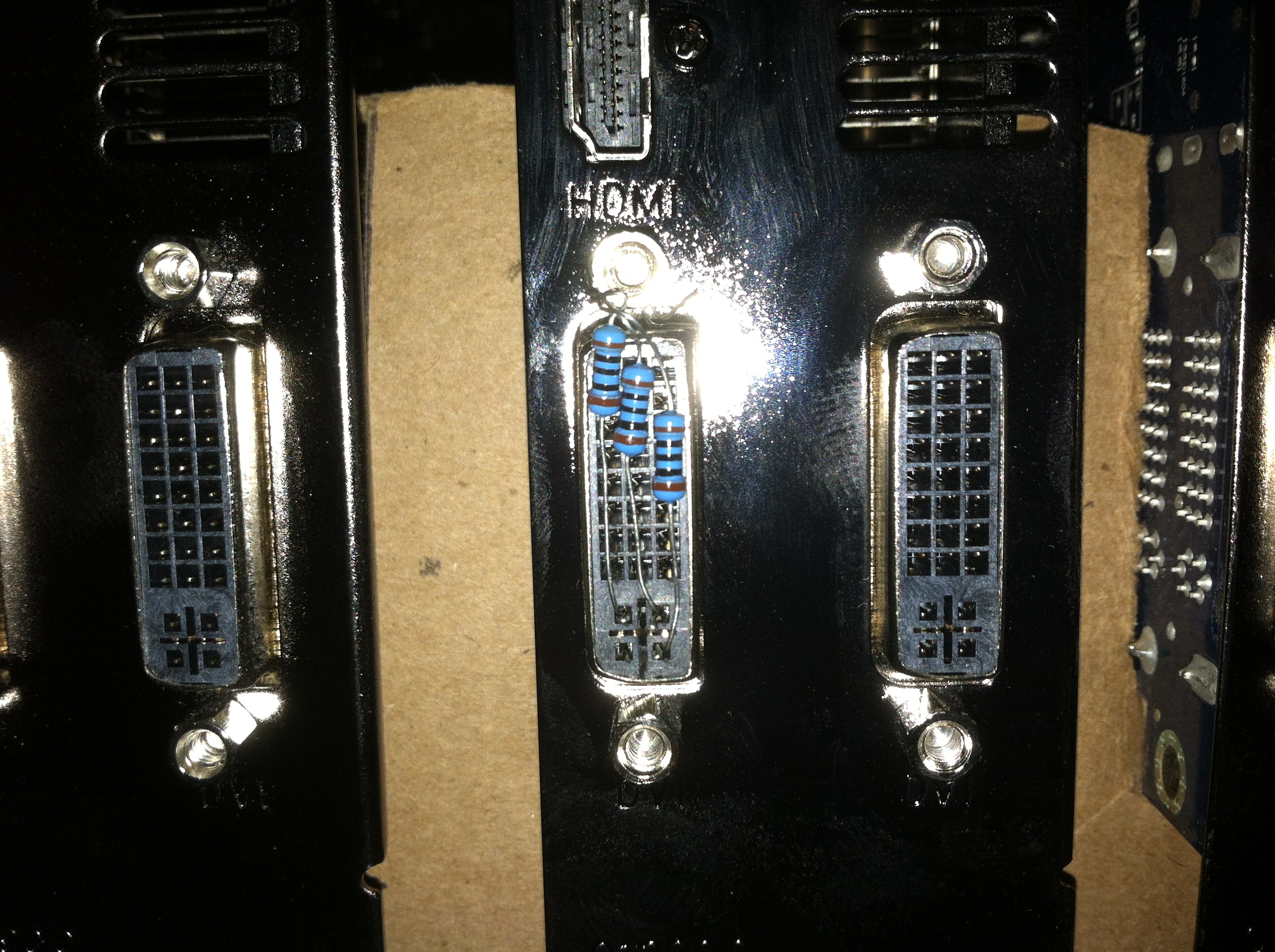
As a way of saving money it is possible to skip using the DVI->VGA adapter plugs as are commonly seen in the mining world and instead poke the resistors directly into the graphics card itself. By unscrewing one of the riser screws on the DVI port it is possible to secure the grounding side of the resistors ensuring the resistors will never shake loose on their own. By laying them down on the profile of the DVI port it creates a profile less prone to getting snagged on other cables while setting up your miners.
First Setup
Powering Graphics Cards
Finding a solution to powering the graphics cards of your mining setup will depend on several key factors such as Watts per graphics card and for most the cost of the power solution. Typically mining setups will make use of a single 1000+ Watt power supply that is capable of running both the host PC and the cards themselves. The power ratings of these units include the other various rails that an ATX power supply uses such as +3.3v and +5v which can come at 30-50 amps apiece. That’s 250 to 400+ Watts essentially wasted since nearly all the power hungry devices in a mining rig will consume the +12v rail.
Server Power Supplies
The Dell PowerEdge 1950 Modular power supply is a considerably cheaper solution for providing 12 Volts at high current loads and can be found for $10 to $15 shipped through sites such as eBay. These units are rated at providing 55 Amps at 12 Volts providing 650+ Watts of reliable power for powering up to 4 graphics cards apiece.
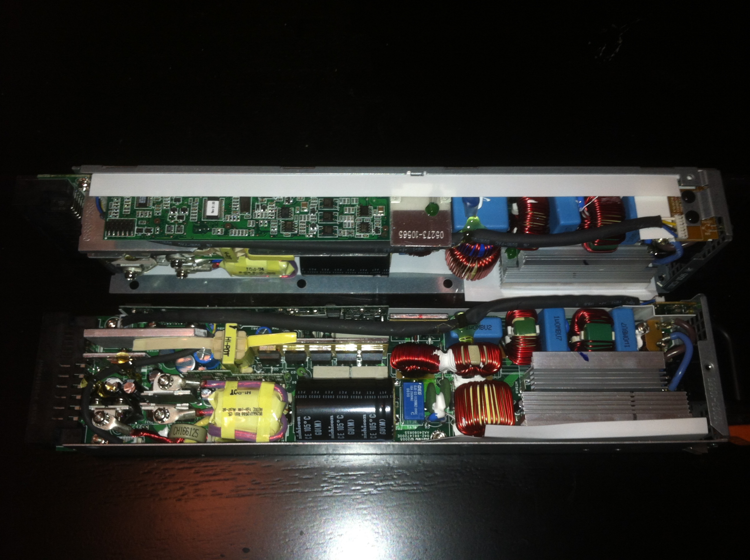
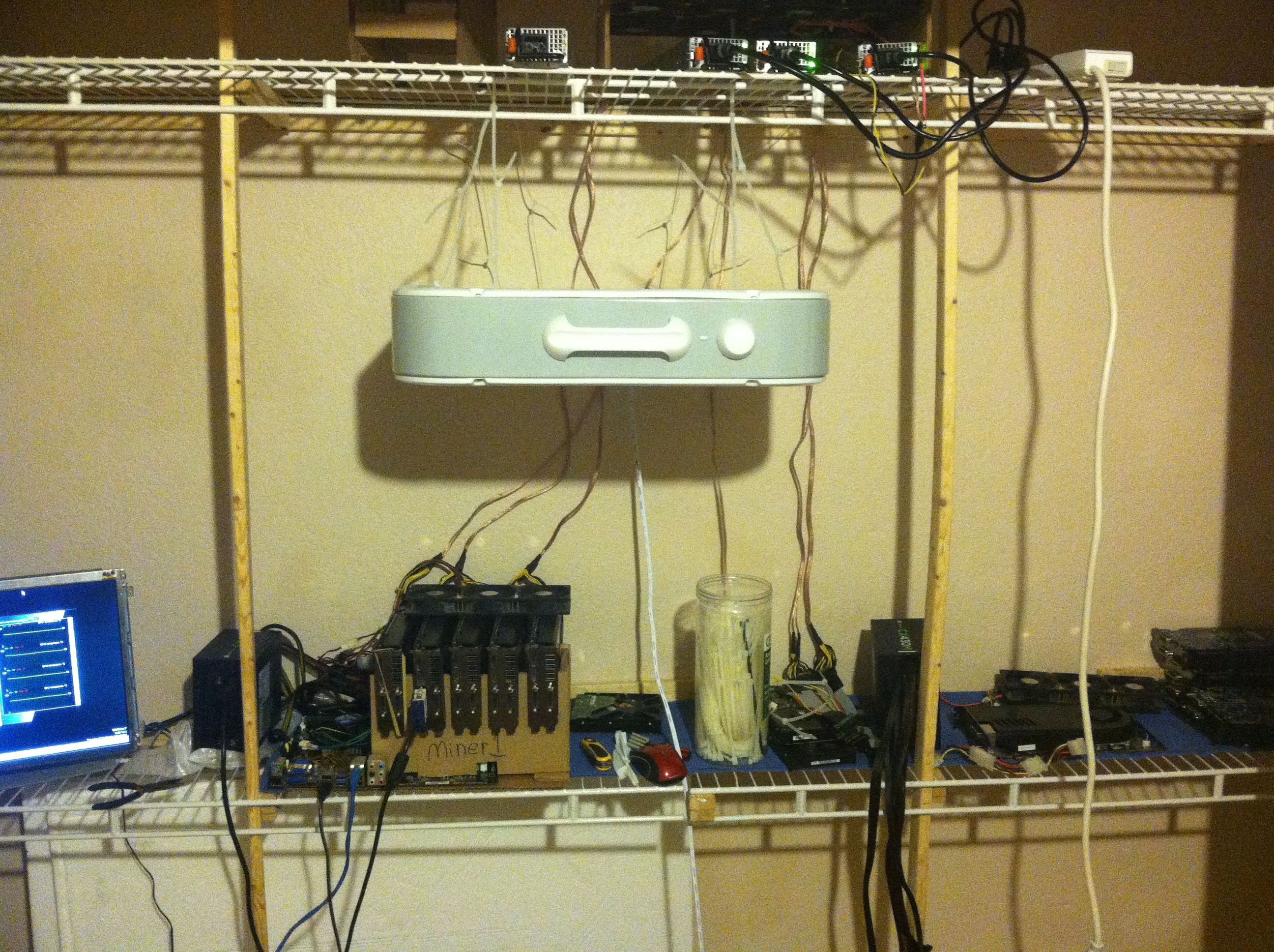
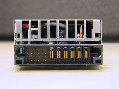
First the top cover of the power supply is removed, these were designed to have air pushed through from one end to the other. Unless you plan on creating a custom modular bay for them or cutting up part of a PowerEdge chassis this is the way to go. Here you also see the modular power connector these use, by using the appropriate mating connector we achieve a swappable power system where if a power supply dies it can be swapped out for 4 cards in less than 20 seconds.
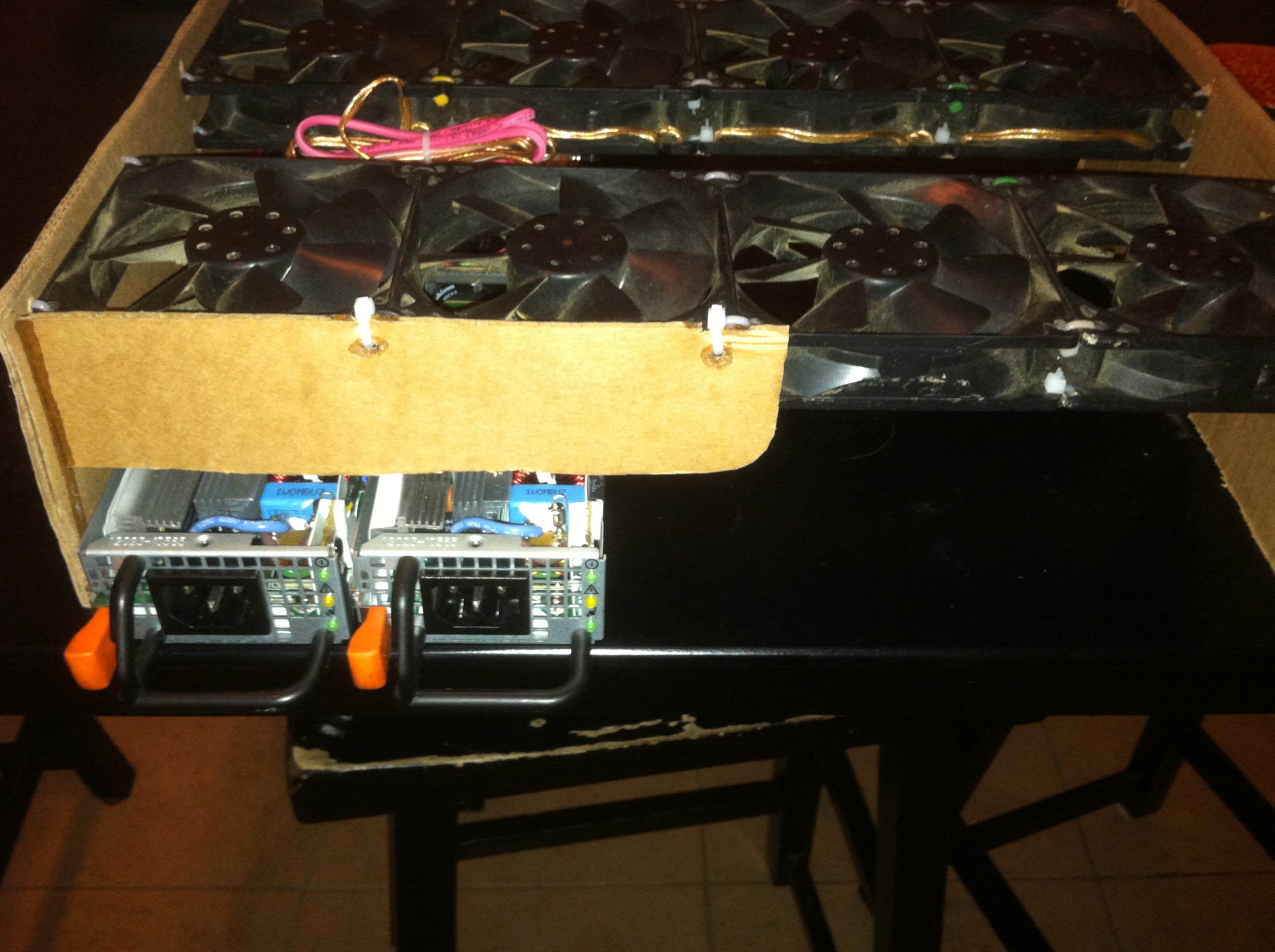
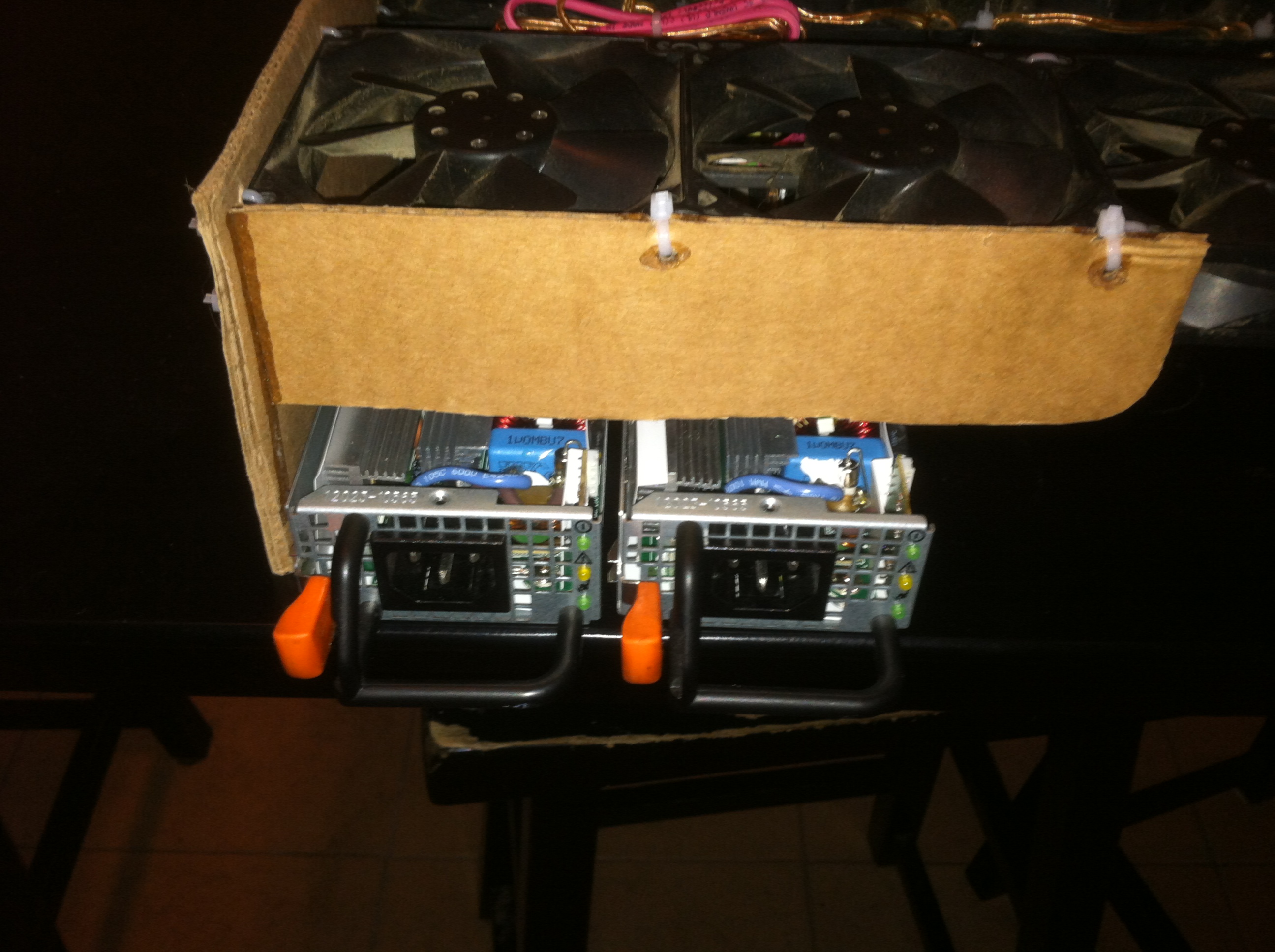
A fan assembly is then constructed that suspends 8x 92mm fans above the power supplies pushing a tsunami of air down onto the heatsinks and other components in the opened power supplies. A total of 5 power supplies will fit under one length of 4 fans stacked side-by-side, 5 power supplies will provide enough power for 4 mining rigs worth of graphics cards or 20 cards total over 5 power supplies.
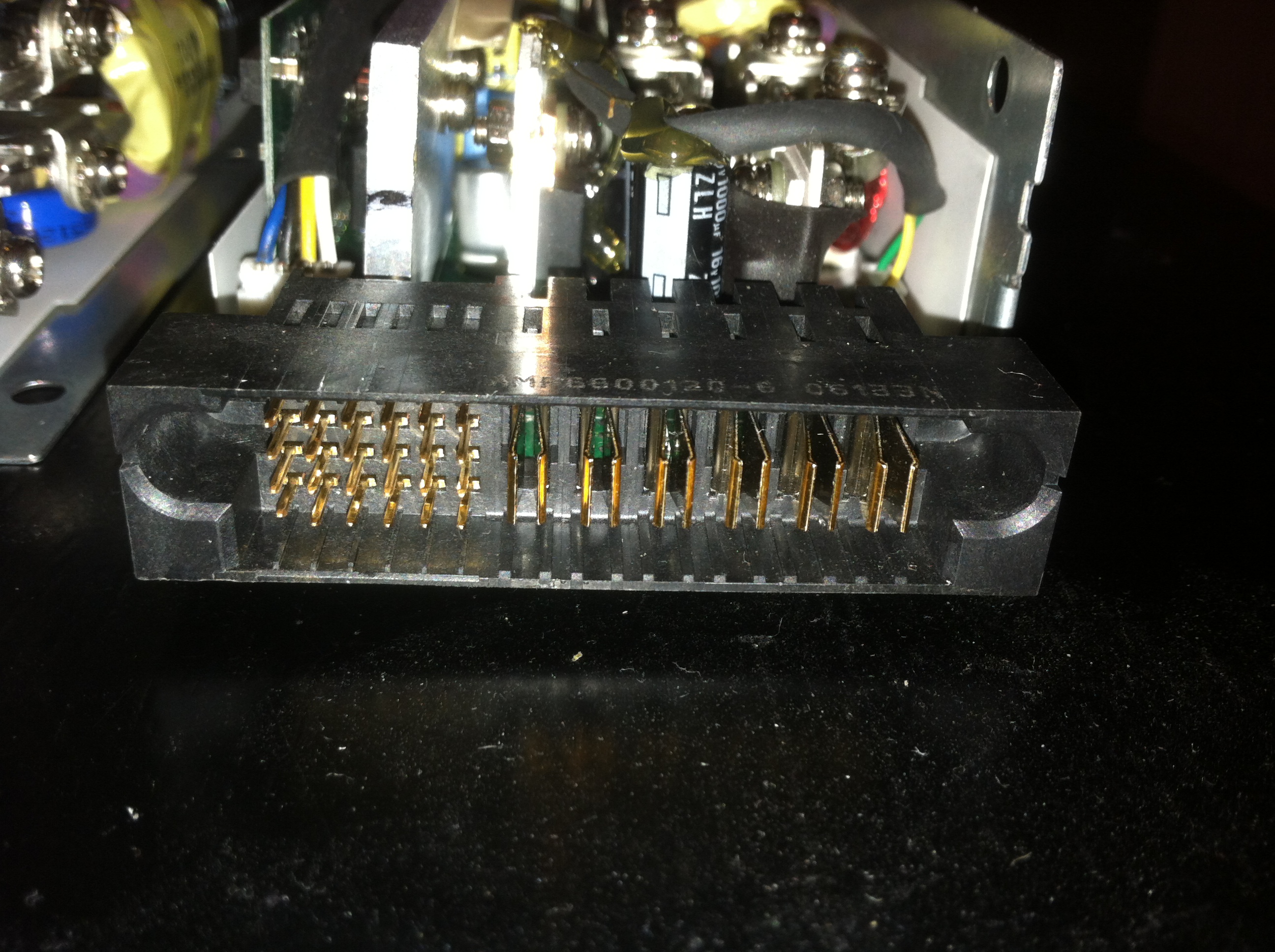
Power Supply Connector
The slightly difficult bit of patching into the pins on the power supply is made much easier by using the mating connector. These can either be salvaged from servers that used these power supplies such as the Dell PowerEdge 1950 series. Another option is to source the actual component itself which can be had for around $8 online or cheaper depending on bulk.

The pinout is somewhat complex however the pins we are interested in are easy to find and once connected together will turn on the power supply and instruct it to output its full power. You can either use a switch between the two wires shown in the pictures below or connect them permanently. You can then connect several units on a power strip and use the power switch on that to turn the units on and off. At one point I had setup a circuit to switch the units on with the host pc being used however the distribution of my power meant I had 3 server power supplies at a max of 12 graphics cards powering 2 host computers running 5 cards apiece. Switching the units on manually before the host PC power is perfectly safe and by not using any additional components here helps keep overall costs down.
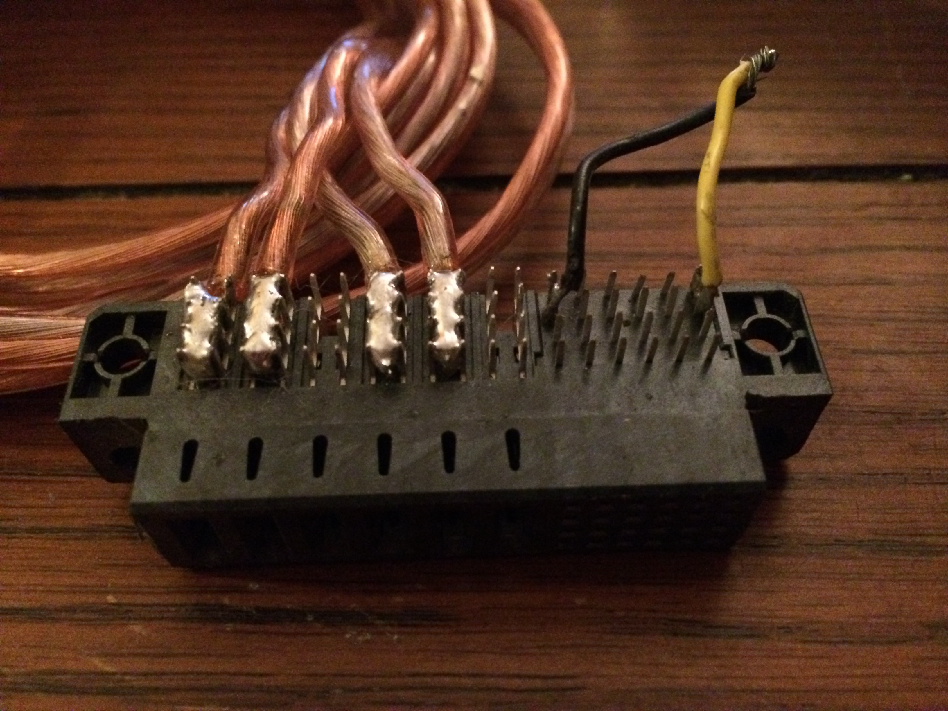
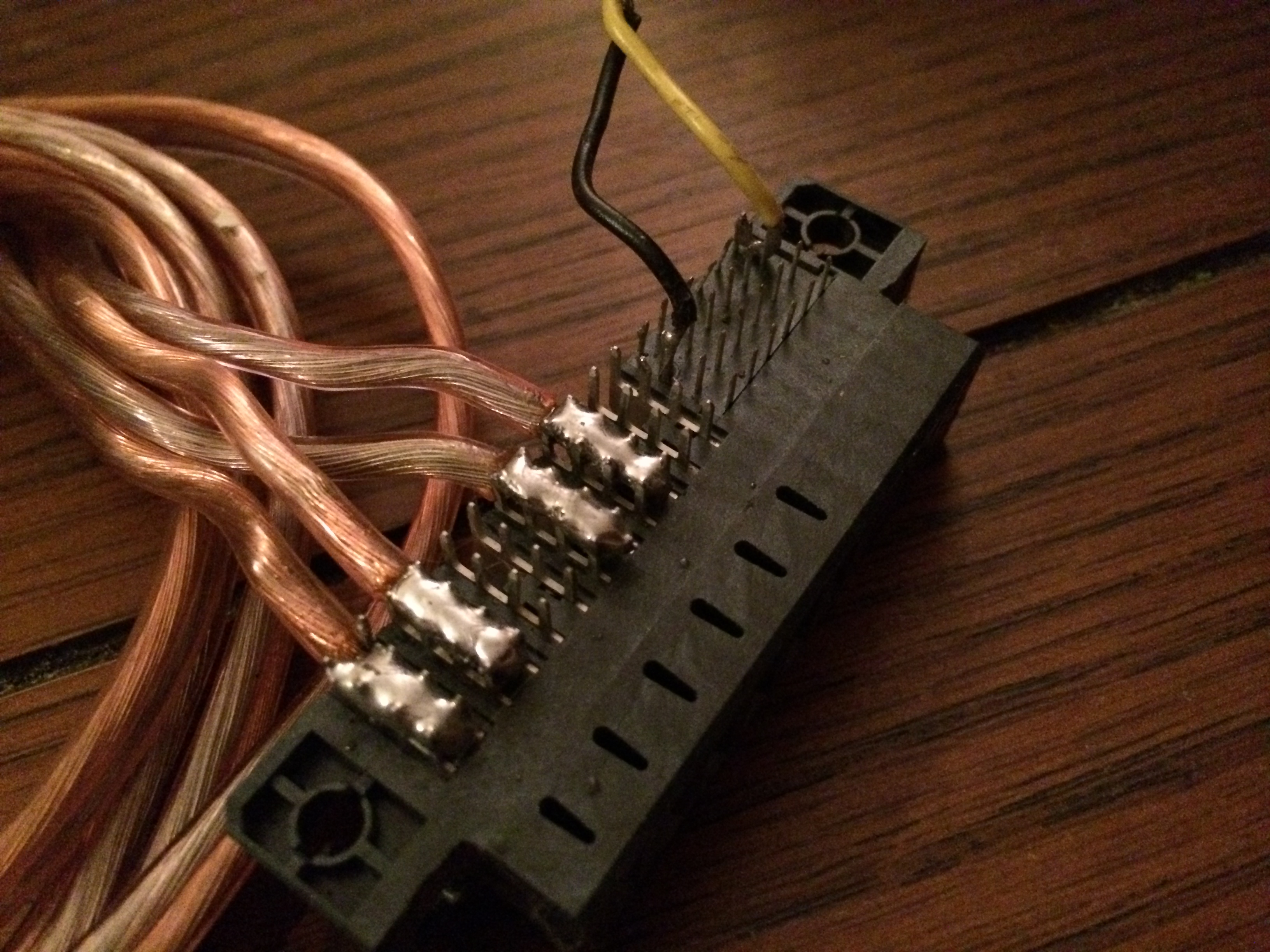
At this point your main power leads to the graphics cards can be soldered to your mating connector with respect to the output pins. The 12v and ground pins are grouped in sets of 3 with a total of 8 pins representing each contact. Wires can be soldered in between the two by four sets of pins to ensure even electrical contact and also make things easier to wire up. Double and then triple check the orientation of the voltage on your wires before connecting the other ends to the actual graphics card otherwise the result could be catastrophic.
The mating connector can be found under the part number G20F203000HR-ND and is made by Amphenol Commercial Products. A quick google search results in quite a few sources of this particular component. Links: Digi-Key, ECIA, and Vertical just as a few examples.
Power Distribution
Reducing cable mess and simplifying connections is a goal of mine for any project. The idea of connecting 4 molex plugs for each graphics card and keeping in mind most of the time people use multiple molex plugs on the same cable/wire makes this a prospect with little in the way of pros and heavy on cons.

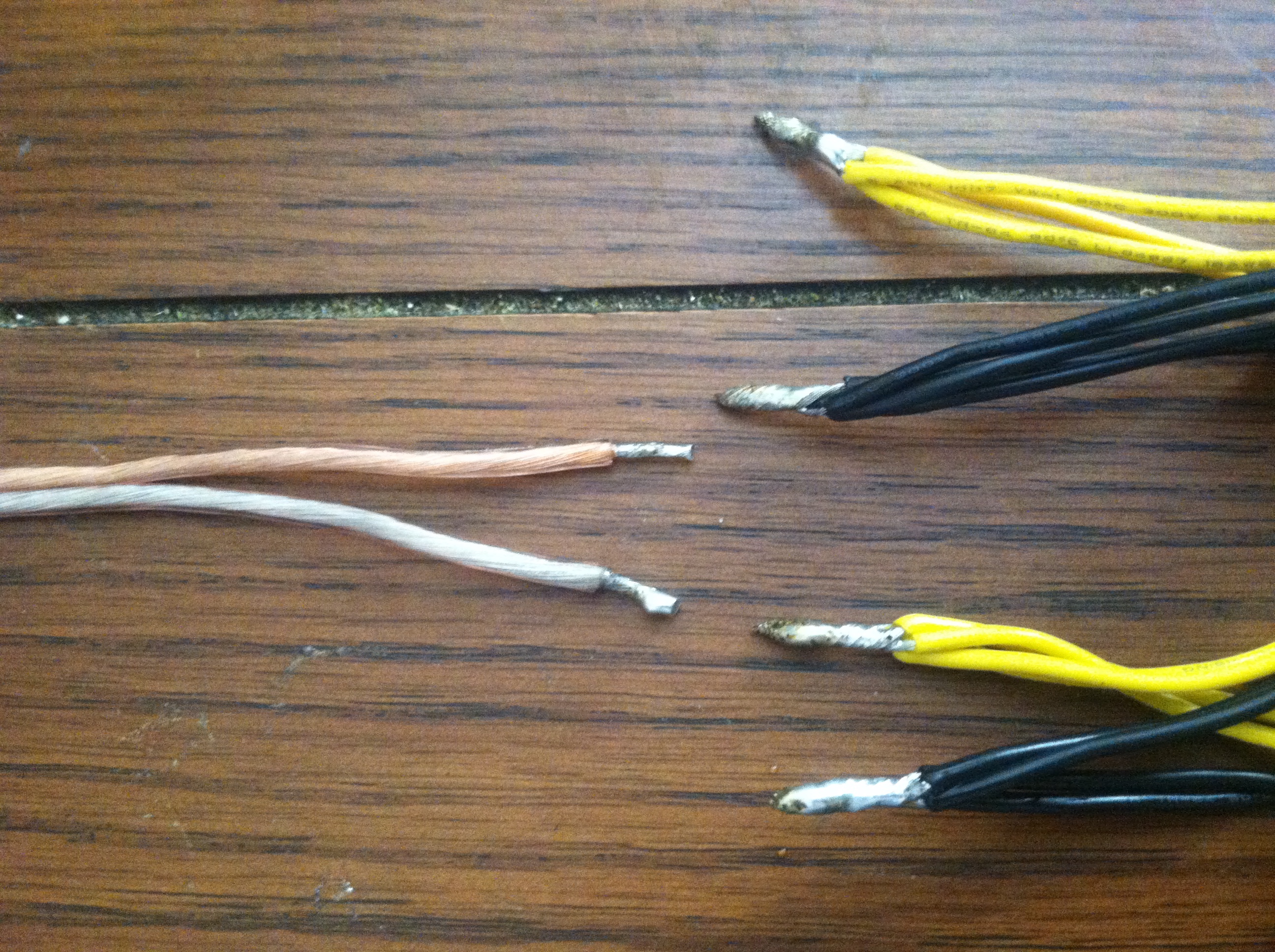
The molex ends of the adapter plugs are cut off and the wires stripped and connected together in groups of 4 plugs or 8 wires in each bunch. It seems like a lot of wires to just twist together but an important factor to keep in mind here is that the specifications for providing power to most graphics cards provides far more than is necessary. Please do your homework, this setup works great for my Radeon HD 5850 series graphics cards, likely cards in the Radeon HD X79X series will require the connectors be soldered in no more than 2 adapters per power lead or 4 wires total.

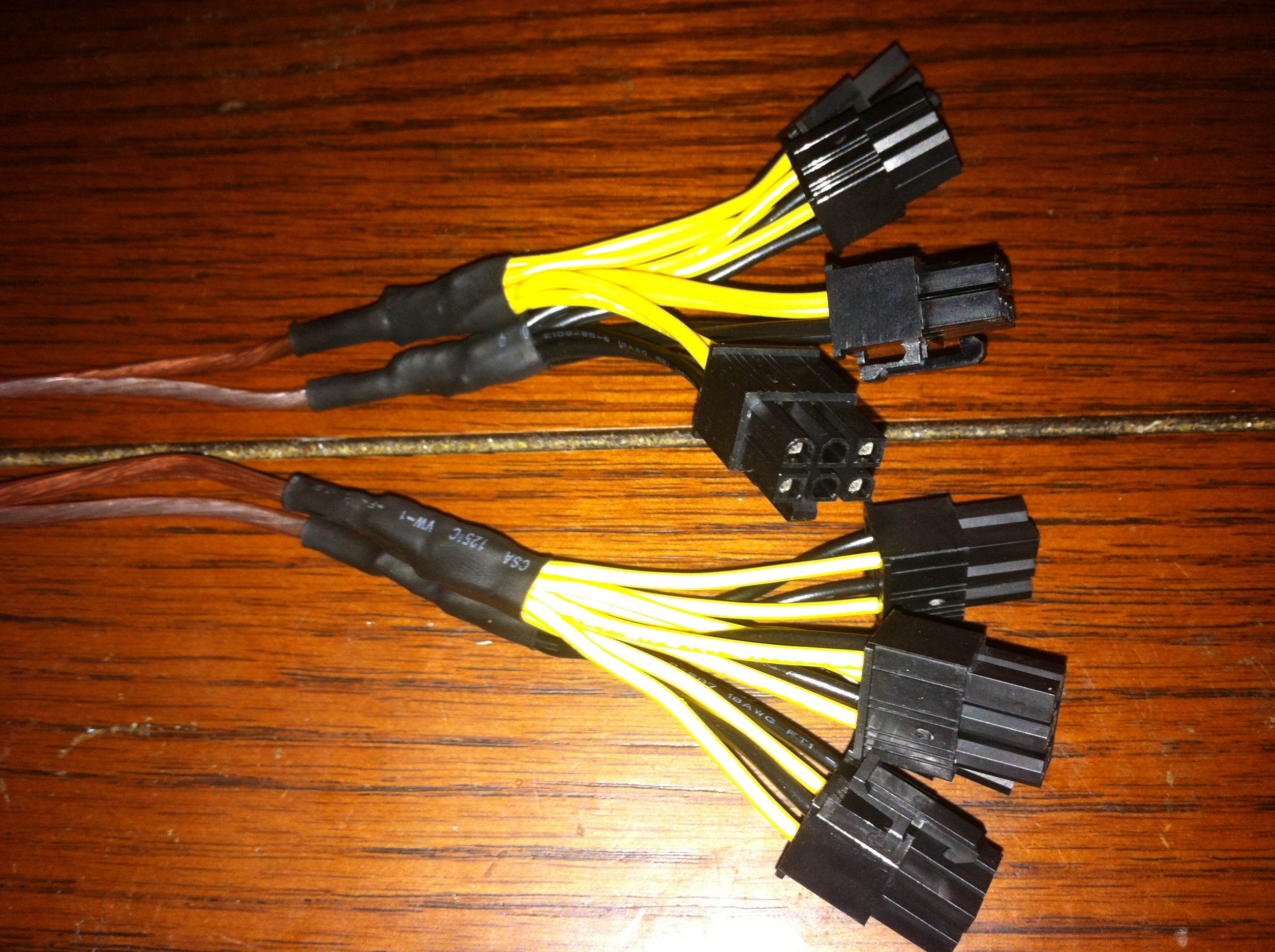
Here is a completed set of power plugs which is enough for two cards, in groups of two these are soldered to the modular connectors that plug into the server power supplies. One additional set (not pictured) is created that only has two plugs or enough for the one extra card in each rig, these could also be used for cards that draw more power.
PCI-Express Power Mod
Speaking from experience no motherboard despite them being designed this way will support the full power requirements of multiple graphics cards. The result is that you will end up burning up the ATX power socket or worse burning a trace or other component on your motherboard. Overcoming this issue is simple and involves a simple modification to the PCI-Express riser cables.
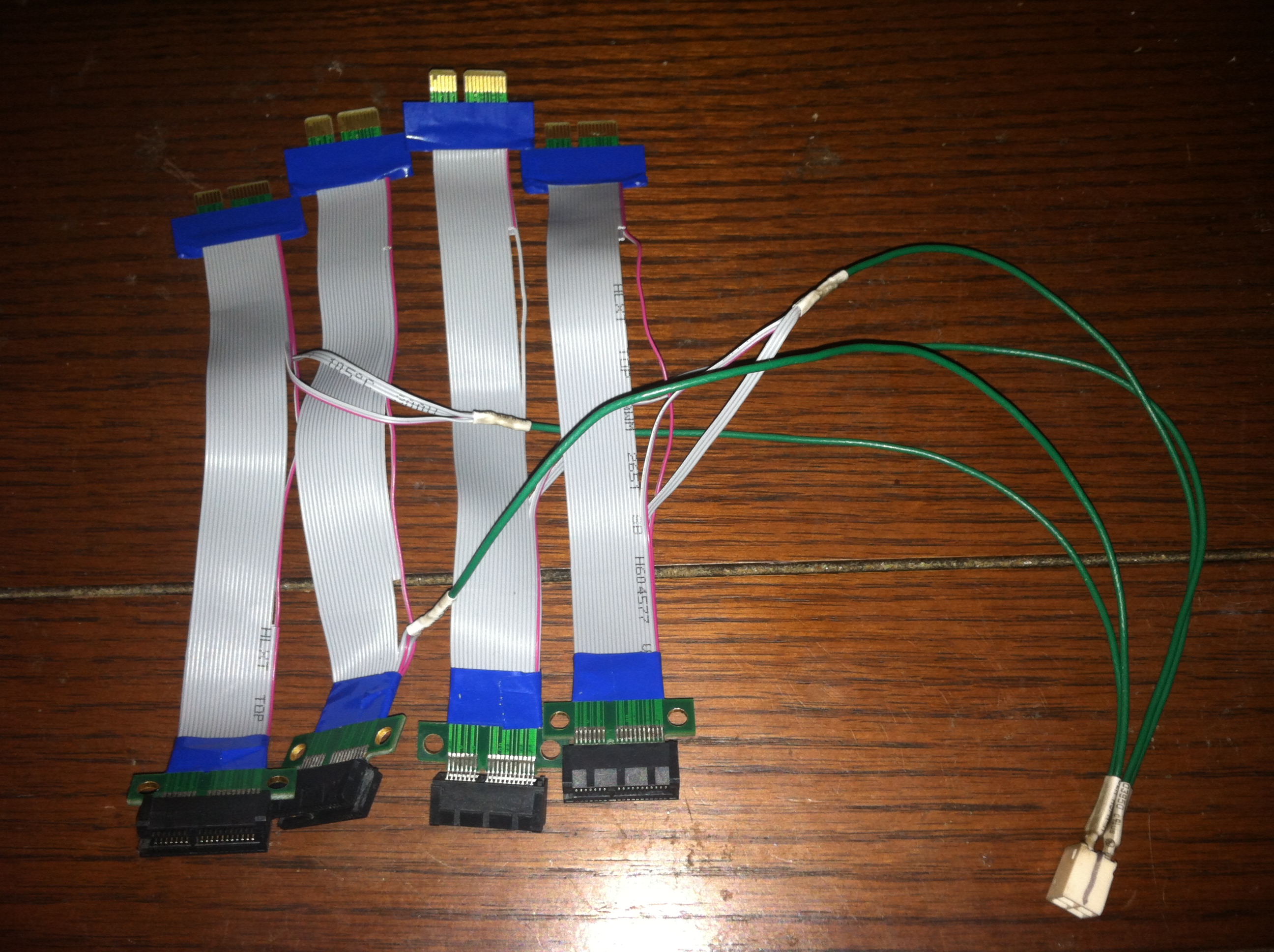
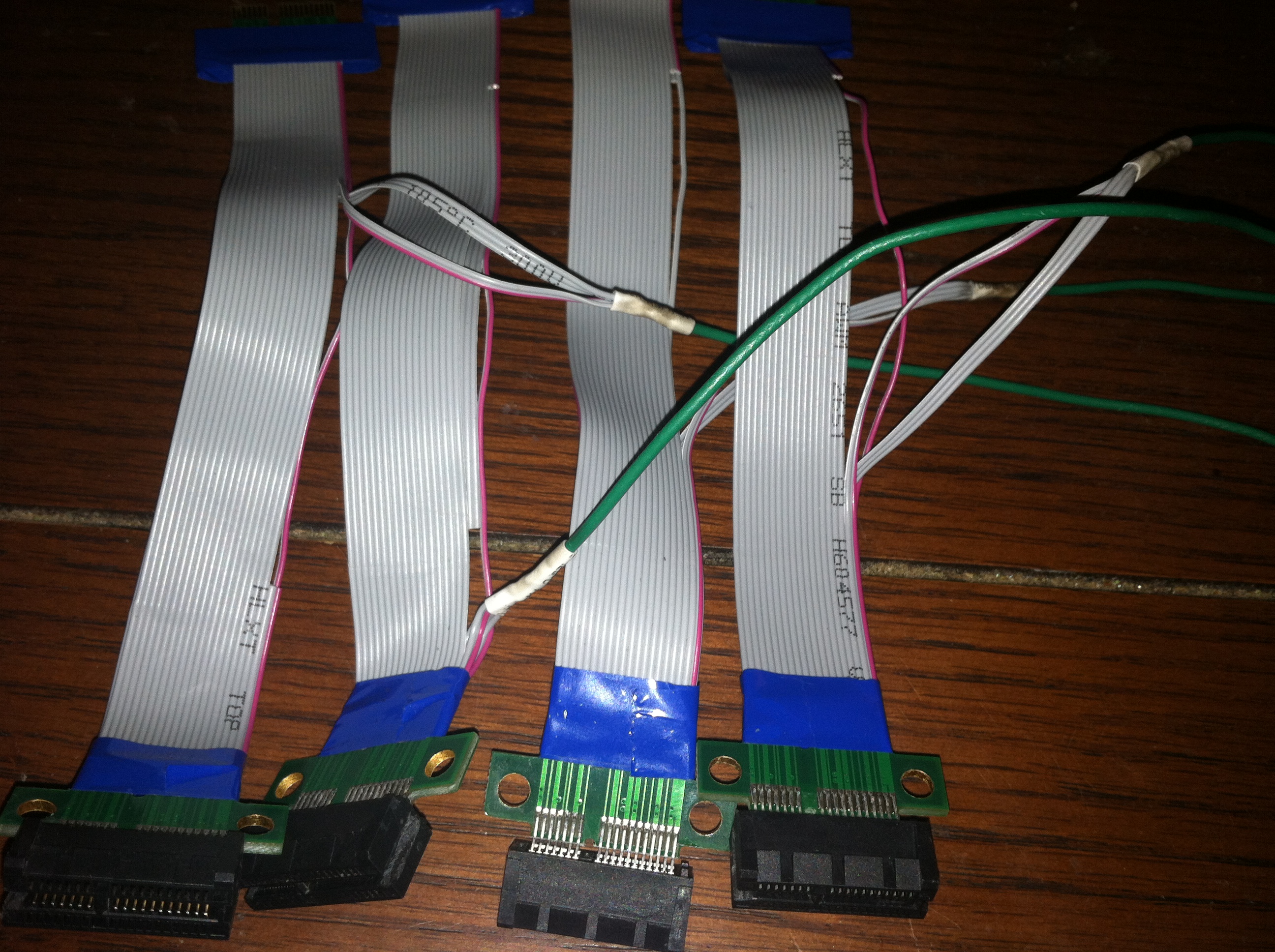
The generally accepted way of performing this mod is to cut back 5 of the wires that run from the riser to the motherboard. These are then stripped, twisted together, and soldered to a length of power wire. A total of 4 of these risers can be safely powered from an atx12v connector with the remaining card using an unmodified PCI-Express riser which draws power from the motherboard. The atx12v connector was chosen since I have hoards of these in my parts bin and the power supplies being used provide two of these for motherboards using the 8pin CPU power, the motherboards used in these rigs only take the 4pin leaving the other 4pin spare.
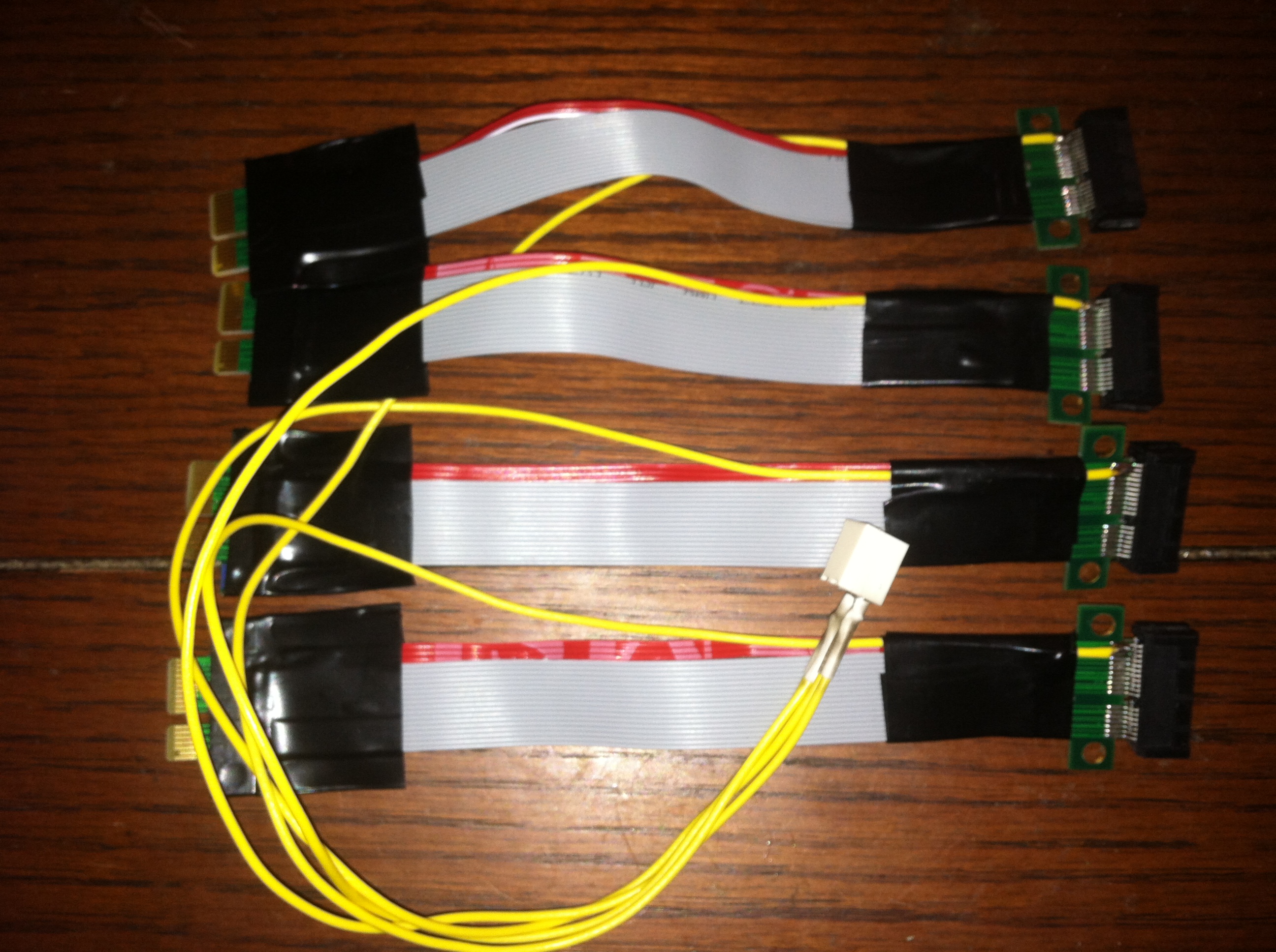
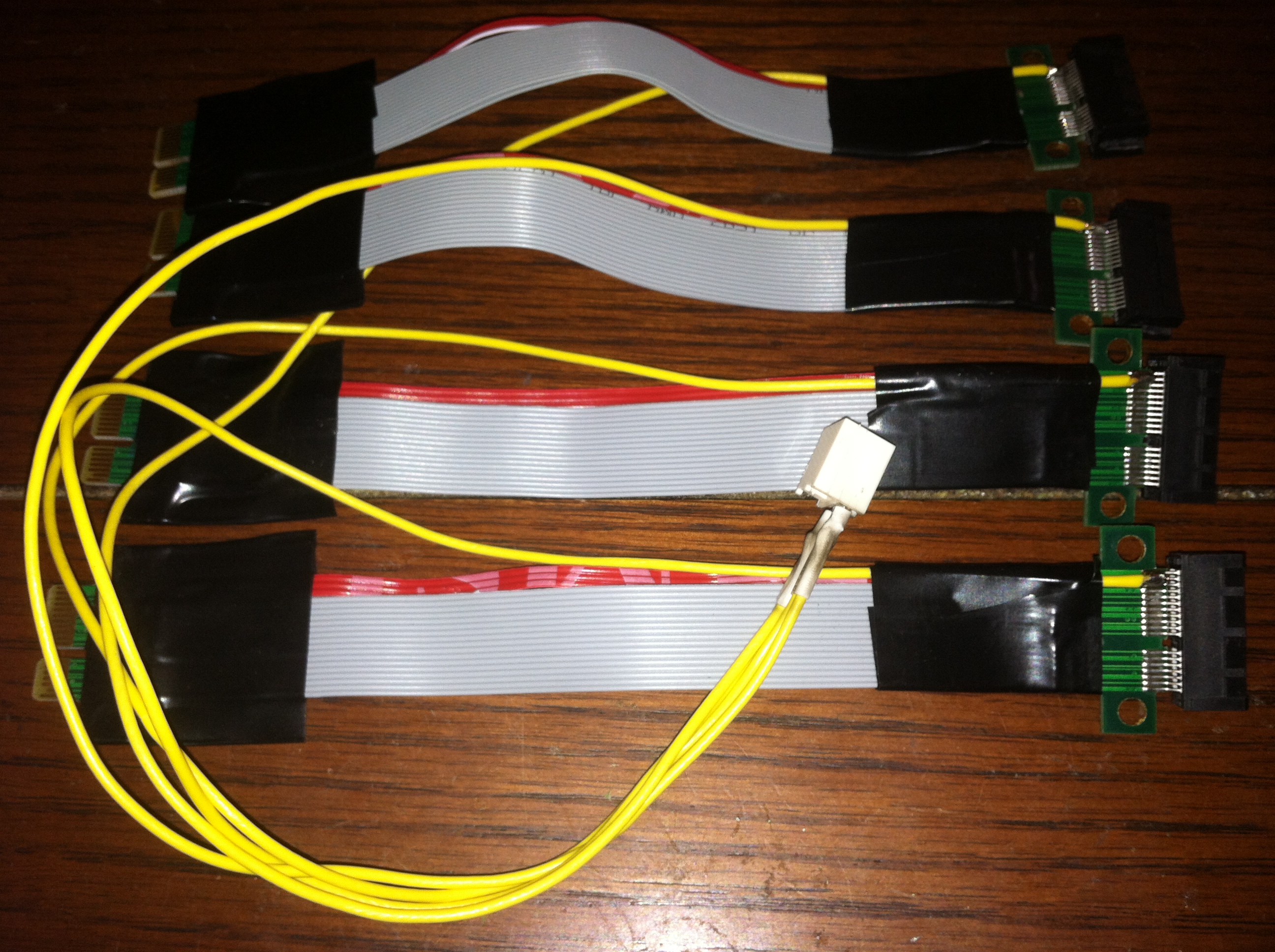
Pioneering a new method I decided to simply create a small cut or breakage in the 5 wires from the motherboard to the riser and then soldering the power wire directly to the riser’s PCI-Express socket. This has the advantage of not trying to send high current through weak ribbon cable and providing a more secure connection point for the wire allowing the riser to stand up to more abuse.
Fixing Fried Traces
Experiencing a complete failure of one of your mining rigs is never a good thing, knowledge is power and experience will teach you important lessons very quickly. It’s not evident to the novice miner that even though power graphics cards have ports designed specifically for the large amount of current they draw that a small portion of that power will also be drawn from the PCI-Express slot. This is likely for the onboard host hardware for the graphics card itself minus the GPU such as the RAM, ADC’s, Fan, etc.. Spanned over 5 graphics cards this turns out to be over 20 Amps of current which is well over spec for the two 12 Volt wires running from the ATX Socket.
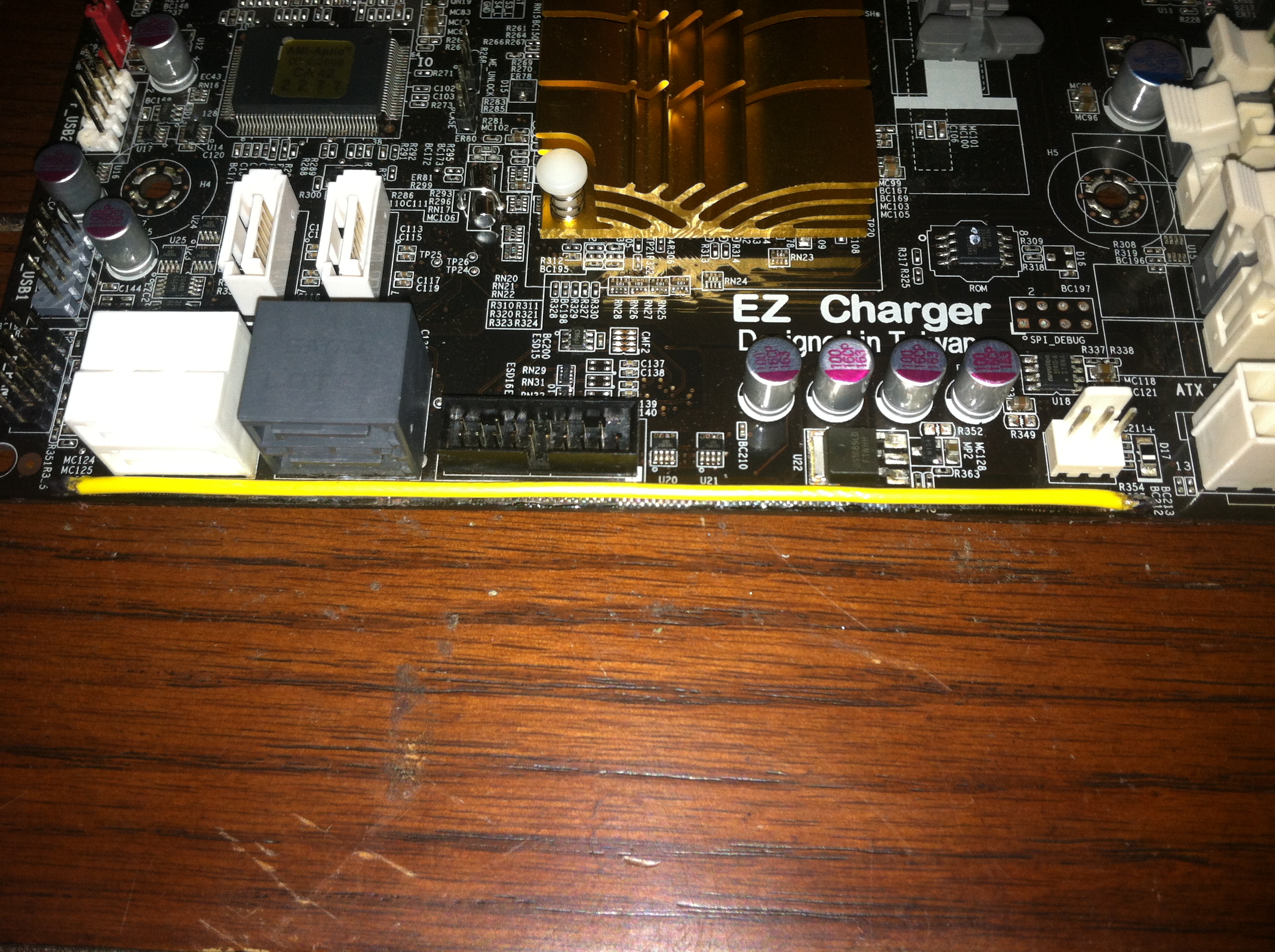
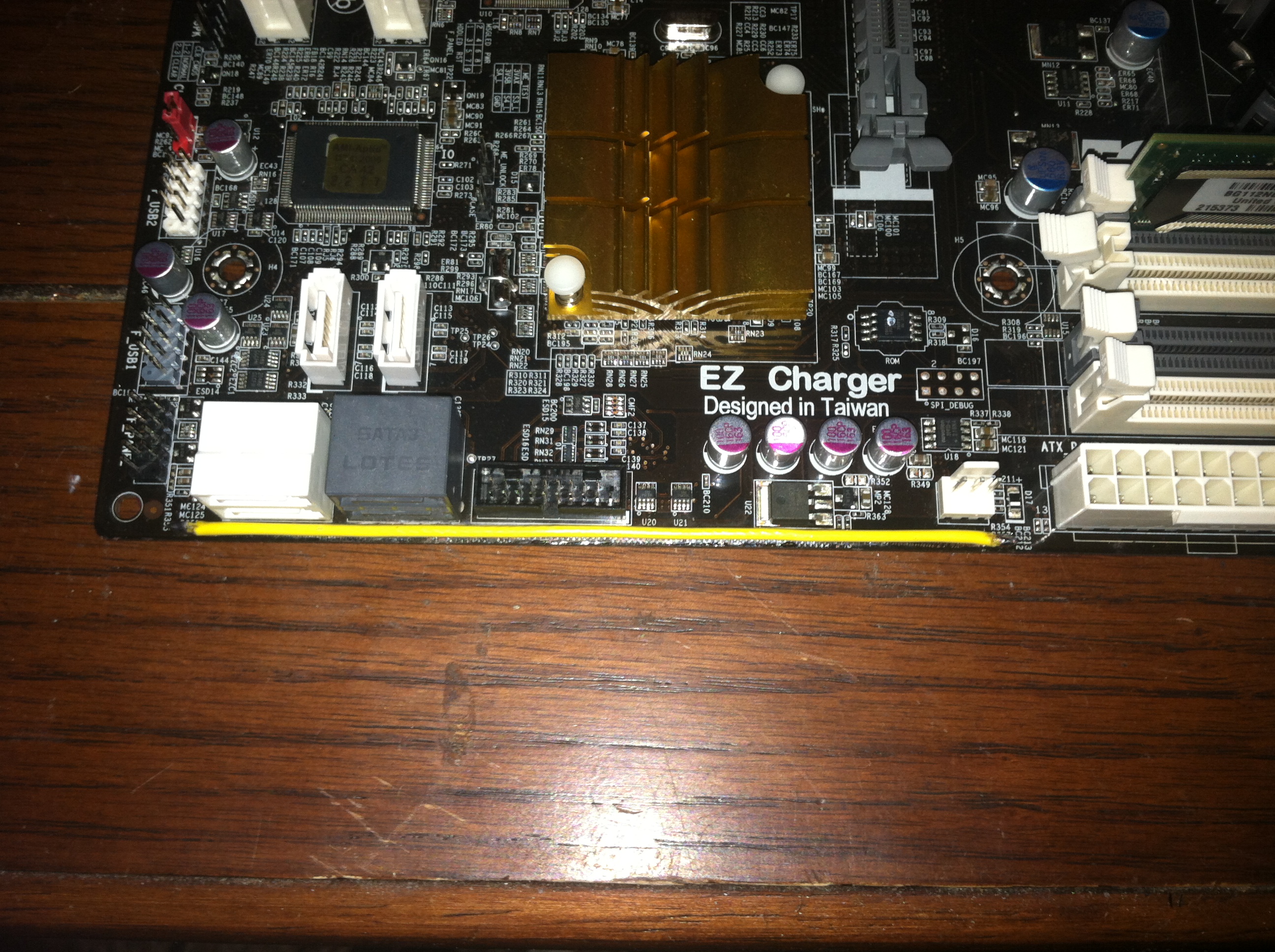
If you have indeed fried a trace on your motherboard it will be necessary to create a bypass of that trace. Luckily on this motherboard the trace ran along a single edge and was easily bypassed by first trimming the burned portion of the trace and exposing some of the intact copper trace at either end. Once secured we can be sure that at least for this portion of the trace the issue will be completely fixed. Going forward as noted above it is necessary to perform the PCI-Express power mod when running multiple graphics cards.