Description
Introduction
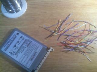
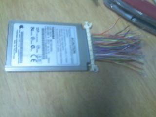
I have seen a few projects interface a desktop HDD / laptop HDD to an iPod and make it work, What I want to do is kind of the opposite. I want to take the hd out of a broken iPod (HDD still works) and interface it to the desktop.
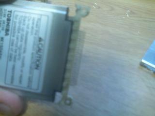
Knowing that the cf (compact flash) interface which is what I presume the iPod uses is IDE compliant it is just a matter of figuring out which pin goes to what and a long and tedious solder job to interface it. Problem I am facing is the hd’s 3.3v input vs a more normal 5v, Id like to use a small IDE > USB adapter. The drive is labeled as a Toshiba MK1504GAL. I am sorry that all these pictures are taken with my Razr, its the only camera I had at the time.
Preliminary Mod’s
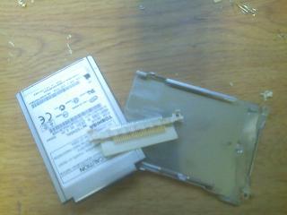
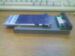
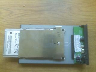
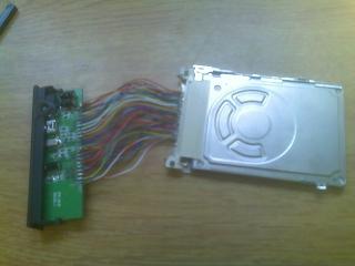
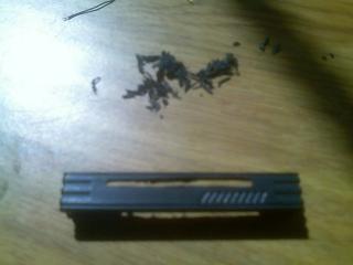
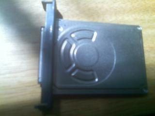
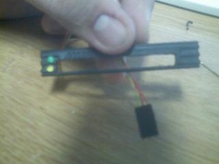
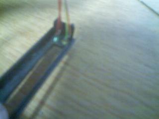
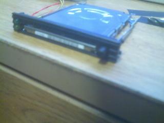
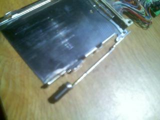
Here are some pictures of the slot I have made for it thus far, I cannibalized an old PCMCIA socket off a laptop. I then removed the pins that did not match up to the interface on the end of the drive. and did some dremeling to get it to go in properly. Just prep work for when I get ready to solder, also the problem of the voltage is troubling me.

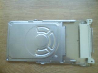

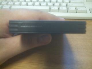
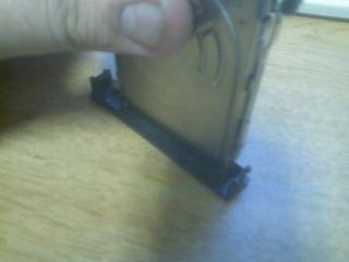
These are just constructing the bay I intend to dock the iPod hd with. My aim is to make it hot swap, and removable so others could be plugged in. Fully constructed dock bay, showing how the drive slides out.
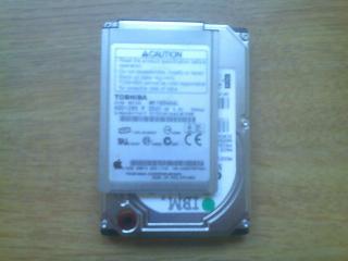
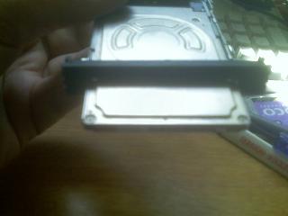
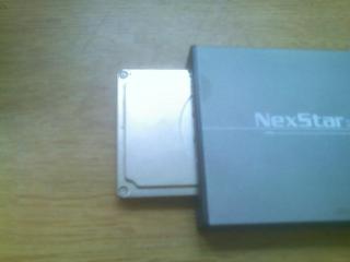
This shows plastic part with the pins, and then a size comparison up against a 2.5” laptop hd.
Soldering PCMCIA Wires
I finally found the correct pinout table for this hd, Although its signal compatible with both IDE, ATA, PCMCIA and CF, it shares the pin configuration of none of those. So some conversion is in order.
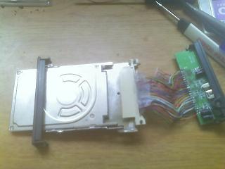
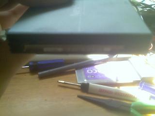
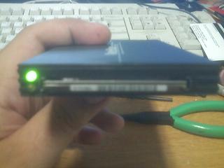
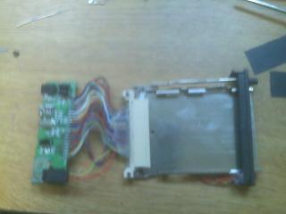
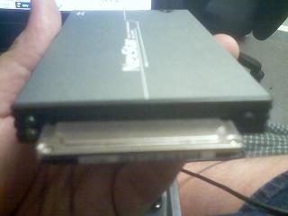
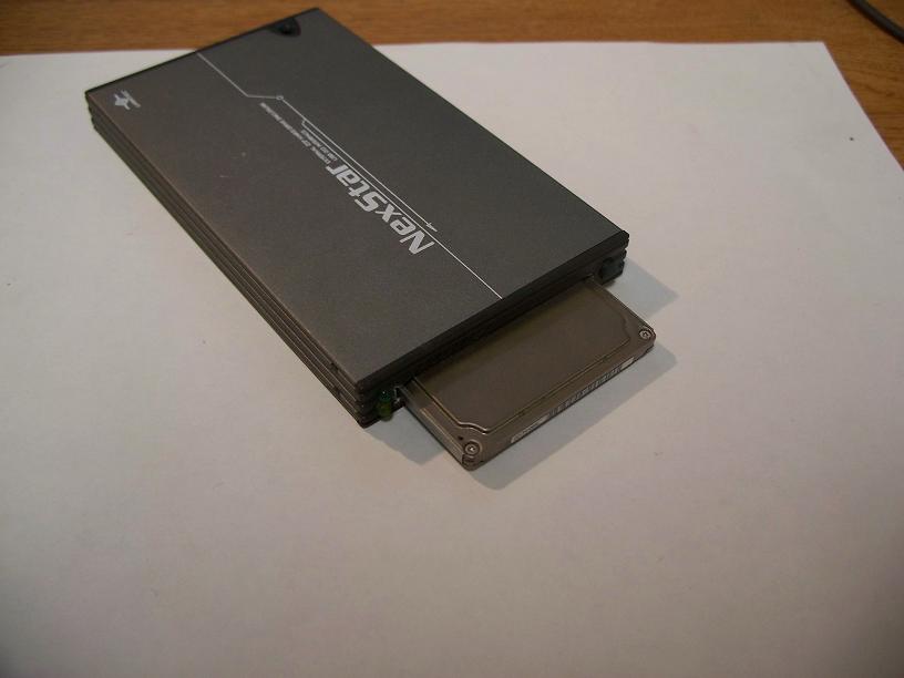
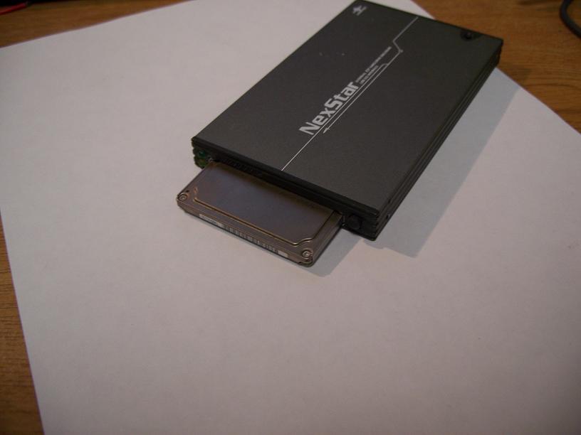
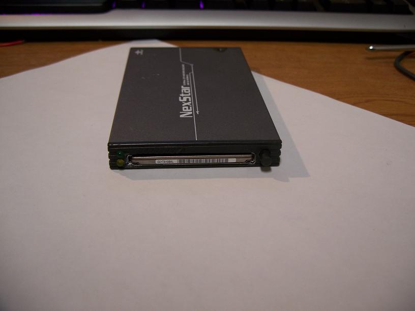
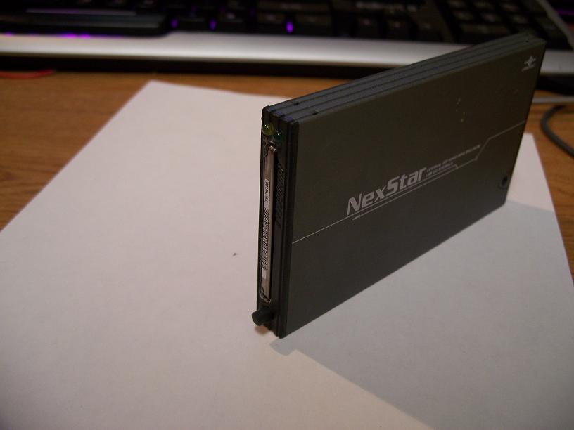
First I was doing some sizing up of the case I may use for this project, its using an enclosure for a 2.5” laptop HDD, and has a IDE > USB board inside it which I will be using to interface my socket to USB.
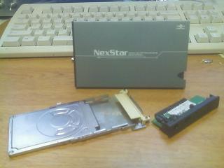
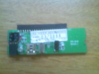
Seems that the whole thing would fit in there with no problem. Showing the parts that would go inside, as well as the little IDE > USB board.
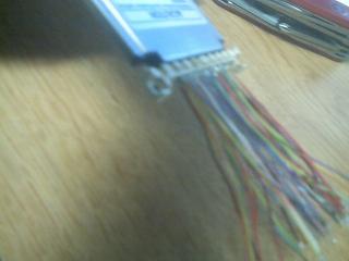
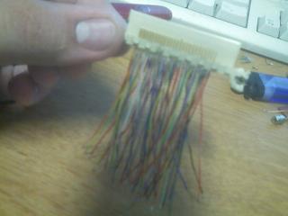
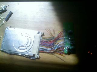
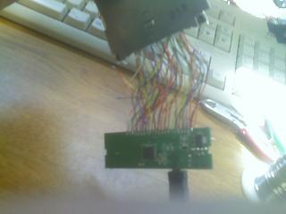
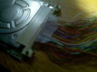
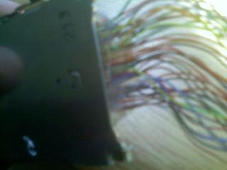
Next was to start the solder process, I had to cut to length strip and tin 50 wires, and then solder them all to the little tiny pins on the old PCMCIA socket. Very tedious work.
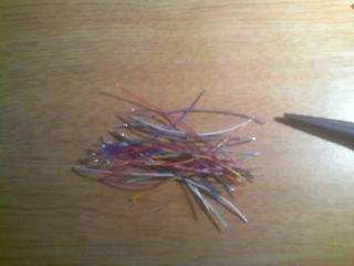
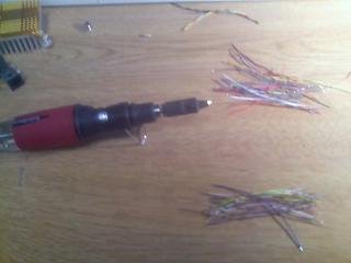
Stripping and tinning the wires. All wires ready, and then an in progress picture of the soldering, with my iron red hot with soldering goodness 🙂 Finished Product, ready for the solder to the IDE board phase:

Pinout Tables
Here are the two pinout tables I am using. I tested the pinouts on my drive and Was able to get the drive to kick on, which must mean the pinout table matches up, The pinouts are for the 40gb drive for the iPod, but it uses the same connector, and I see no reason why it would not be the same for mine. or for all iPod HDDs for that matter.


Also here is an image of the pin assignments for the HDD.
Prepping and Soldering IDE board
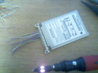
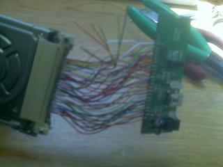
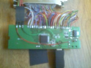
I went ahead and started to solder the wires I had soldered to the modified PCMCIA socket to the converter board for IDE to USB, took a while but was able to do it without a hitch. Turns out its basically a direct pin compatibility with the ide interface on the board itself, so pin1 on the pcmcia socket (apple hd) to pin 1 on the ide board, and so on, basically i just made the judgement call to go ahead and feed the drive 5v instead of its 3.3v its been running for hours with no issue, I may make a small circuit just to be on the safe side to feed it 3.3v but its not mission critical, I kinda had the feeling it would be happy with the 5v as it seems compatible with the ide (laptop side) interface.

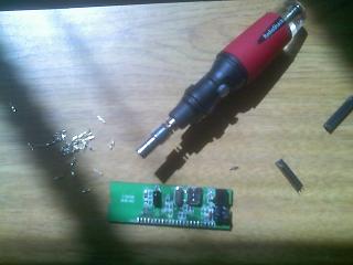
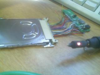
These show me desoldering the Laptop IDE connector off the board, and the latter it completely removed. I did this by carefully pulling the plastic piece off the little gold pins, as it would be pretty difficult to desolder 44 wires at the same time, I just did it one by one, I used my torch to melt the solder and they fell right off, took like 5 minutes. These are in progress shots of soldering the wires from the pcmcia plug to the ide board, and then a shot of all the wires soldered, The few that are left unconnected are the Master / Slave wires, which I later removed, Just were not needed to make it work.
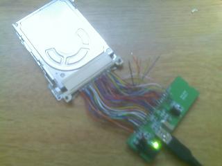
This is where I finally hooked up the USB cable to my computer, Magically it detected the drive and mounted it (really happy).


Now for the proof that It actually did work may any of you be skeptical. And this is the drive after I formatted it. The interface seems to be extremely fast, for a HDD of this physical size, and for something I soldered its quick. Took about 60 seconds to copy a 700meg movie over to it, can’t be unsatisfied with that.
Preliminary sizing up of the hd to the front bezel
Just some preliminary mockups of how I want the drive to be ejected, also how I want the drive to come out of the front of the enclosure. My plan is to cut a small (PCMCIA card) slot for the drive to slip into in the front, and have an ejection switch similar to that of a laptop and its PCMCIA socket.
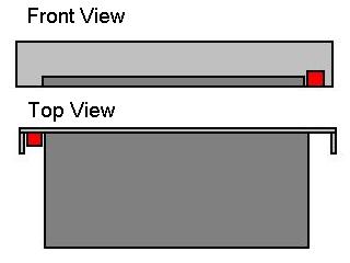
Picture of the front, and then a picture of how the drive looks up against the back of the front piece. Dark grey is the iPod HDD and socket assembly, Red would be the ejection. Light grey is the actual front piece.
Cutting slot in the enclosure
I had to go ahead and put some hot glue on the PCMCIA socket as those connections are really flimsy and fragile, Replaced a few wires that were being a problem, and all is happy.
Next of course comes the long and boring task of dremeling and using my Xacto knife to cut a hole in the front bezel. Preliminary cuts on the bezel, and then we start to see the drive ad poke through a bit.

Finally the drive and its bay fit in the hole. Just a side note: I am actually mounting the bay flush with the outside of the bezel reason being that if the bay is mounted internal and not flush on the outside the drive sinks about 2mm into the enclosure, and then you cannot push it in fully, so id rather have it flush. Plus it make sure it docks right when you put it in the first time. Before and after shots of the bezel on the front, its not pretty yet, more work to do to clean it up.

Now time for some glory shots 🙂
Adding LED’s
I have decided to add HDD power and activity led’s to the front of the enclosure, all good enclosures have them, so why not mine. In all truth there already was a bi-color led at the top of the enclosure near the usb plug, but it is hard to tell when it is active or not. I prefer to have the different led’s, and at the front of the enclosure where my drive and eject button are/will be.
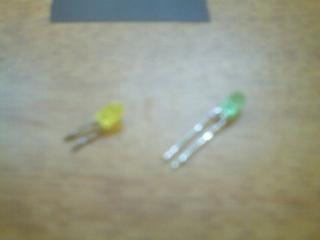
So first of all I needed to find the LED’s I was going to use, rummaging about in my spare parts box, I found a little header which had two led’s I desoldered off a dead network appliance. I then took those out of the casing and ended up with a yellow and green led (green for power, yellow for activity).


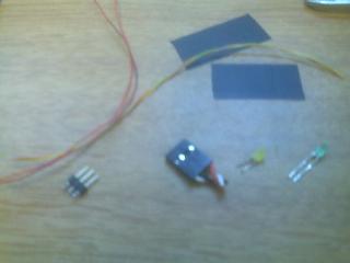
Next was to start work on the cable to attach to the led’s at the front.
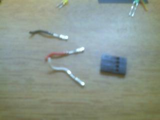
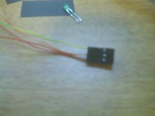

I took the pins out of the salvaged CDROM audio cable, and soldered my wires to the pins and then put them back in the connector. Then I soldered the LED’s to the ends of those wires.
Next was to figure out how to connect this thing to the PCB. easy solder the middle pin of the 3pin header I had to the bottom of the board which was the same ground as was connected to the middle pin of the bi-color led. After which I just needed to run two wires from the header to the legs on the led.

Next was to get holes in the front of the enclosure for the led’s easy work with my little hand drill to get the pilot holes, and then i used my Dremel to widen them just a bit. turned out very nice.

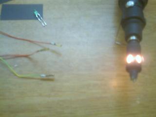
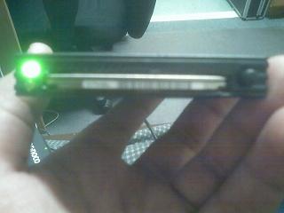
Now for the glory shots of it working! They are not quite that bright in person, but they do work amazingly well, I am quite pleased with the outcome of this phase.
Wrapping up
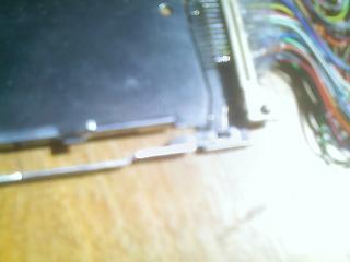
I finally convinced myself to figure out the eject button, just due to how the apple hd differs from a normal PCMCIA card caused issues, as well as making a button for the rod that connected the eject mechanism to the button. I figured for the button I would want something round but similar in color to the enclosure, after looking for a while nothing…. but wait, is that the back end of a old useless drill bit? I think so!!!!


Just a few extra glory shots of what the insides look like, and then some final shots of the button in action.
Eject mechanism better explained
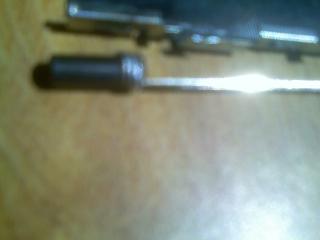
The Drill bit is a 3/16 inch bit. Its one of those crappy bits you can get in the check out isle of Lowes. for like 99c…. After about 2 uses its too dull to drill through air.. if you get what I mean.
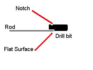
Actually the eject mechanism keeps the push button from falling out of place. This is kind of weird but bear with me. The way I attached the drill bit to the rod that connected to the eject lever was to first Dremel a flat surface on the last 1/4 inch of the bit then I dremeled a small notch on the other side. Wrapped that with some single core copper wire, and soldered away. The idea is that rosin when it cools will act as a super glue to hold the two metals together. also the wire wrapped around it provides extra strength. as the solder will get down into some of the crevices and keep it from moving around. Its very very strong. and keeps the drill bit from moving backwards or forwards. the only movement it can make is the same that the rod can.
At the connector end of the PCMCIA socket is where the rod connects to the lever that pushes the drive out. the way its connected prevents it from falling off, or moving around except for the push in and out motion of the button. It will only go as far as the lever that pushes the hd out will let it go.
Better Pictures
Final Thoughts
It was a fairly difficult project, but well worth it. I am also doing song recovery for people who have the 3g-4g iPods who break their screens and whatnot on campus here, so its nice to have a very simple device to get the music off.