Description
At the time of writing, my current employer Zimmerman Advertising has a meeting room where the various team leads for a given project can meet to work collaboratively and hash out important details. We call this room the War Room. As one might expect in the War Room things can get heated as debates happen over functionalities, implementations, and user experiences. I realized it would be handy to have a visual indicator of the threat level readiness of conditions in the War Room.
Introduction
DEFCON or Defense Condition is an alert system utilized by the United States Military and indicates a level of alert ranging from DEFCON 5 (least severe) to DEFCON 1 (most severe). The goal of this project is to create a Defcon sign in the same manner that is driven by simple commands sent to a particular twitter handle using a Raspberry Pi as the controller.
Finished Project
Pictures go here -__-
Inspiration and Source Material
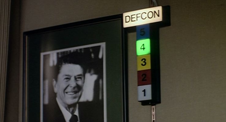

The Defcon sign has been seen in many films and other media with some of the most notable being the 1983 film entitled WarGames which is pictured above.
Shown in WarGames are two styles of numbering with the first being simple black lettering on top of colored squares, the second being a colored number with a matching color border. I like the look of the second option and since I will be printing the designs as overlays will mean a minimal amount of extra work to replicate.
Frame
First it was important to either build a frame from scratch or modifying an existing frame to house the numbers, Raspberry Pi, and other control components. This meant the frame would need to be at least an inch thick and about 2-3 times as wide as it is tall as the numbers will not be perfectly square to start with.
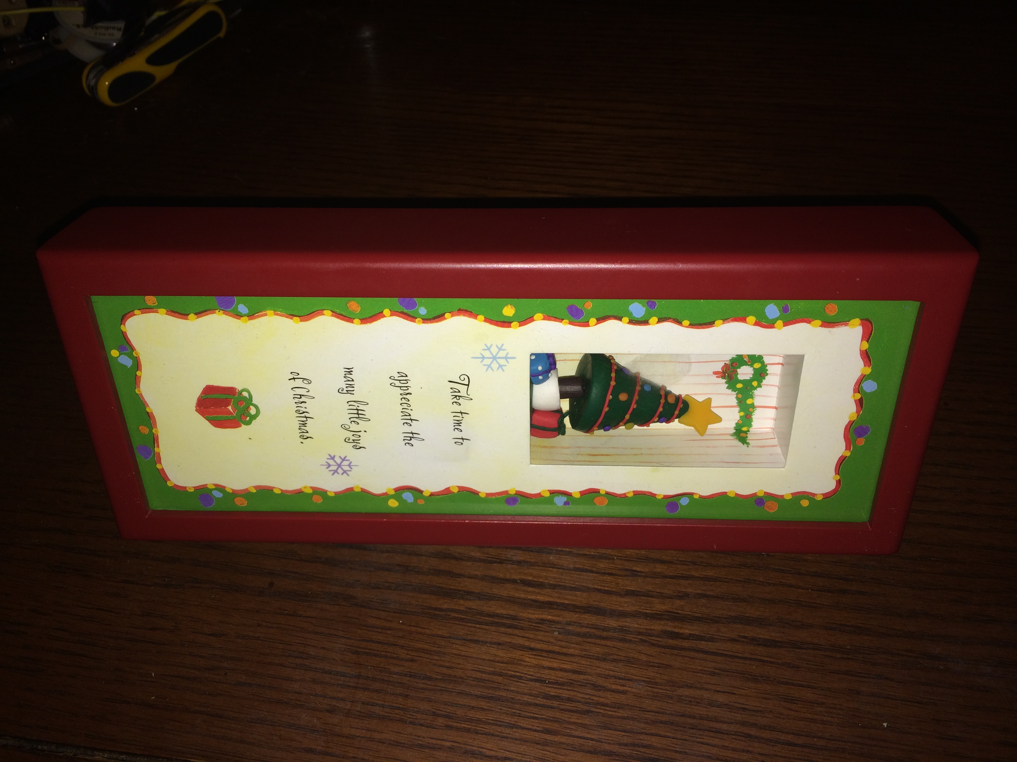
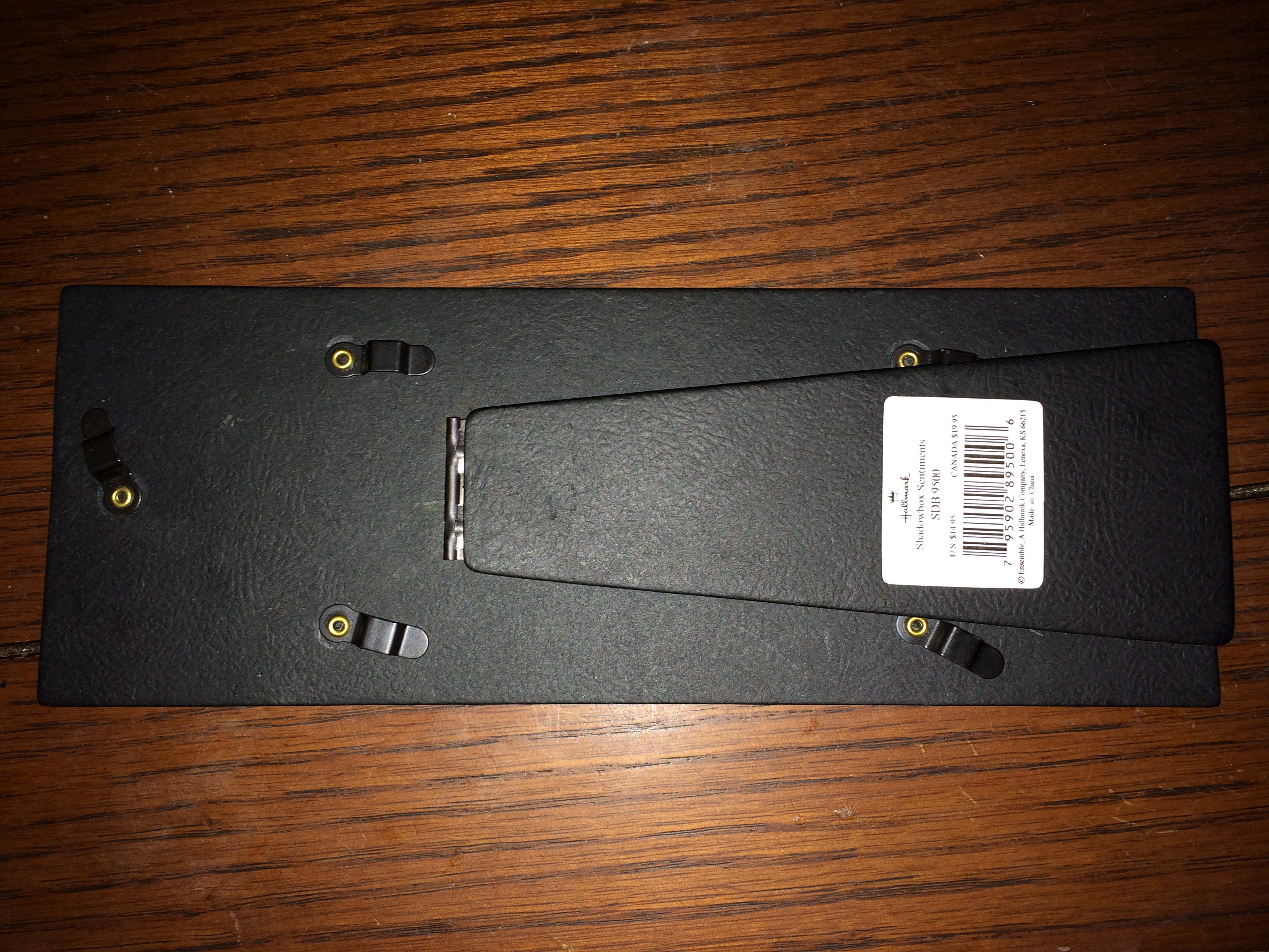
Luckily I was able to find a second-hand Hallmark Shadowbox Sentiments that roughly matches the red color used by my current employer and is 4 inches tall, 10 inches long, and 1.25 inches deep. These frames can be found in black as well and they all appear to come with various themed bits inside that I simply discarded.
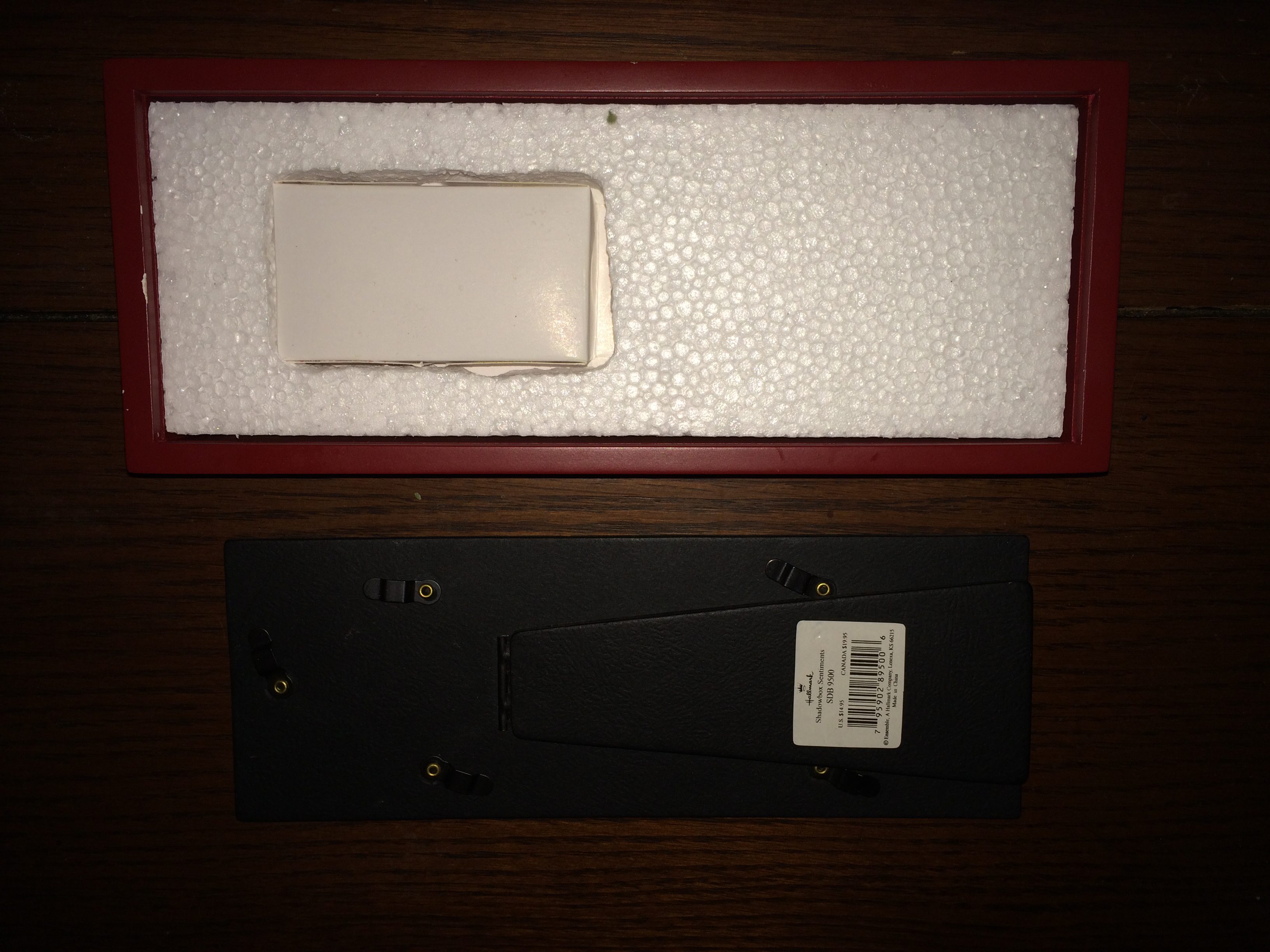

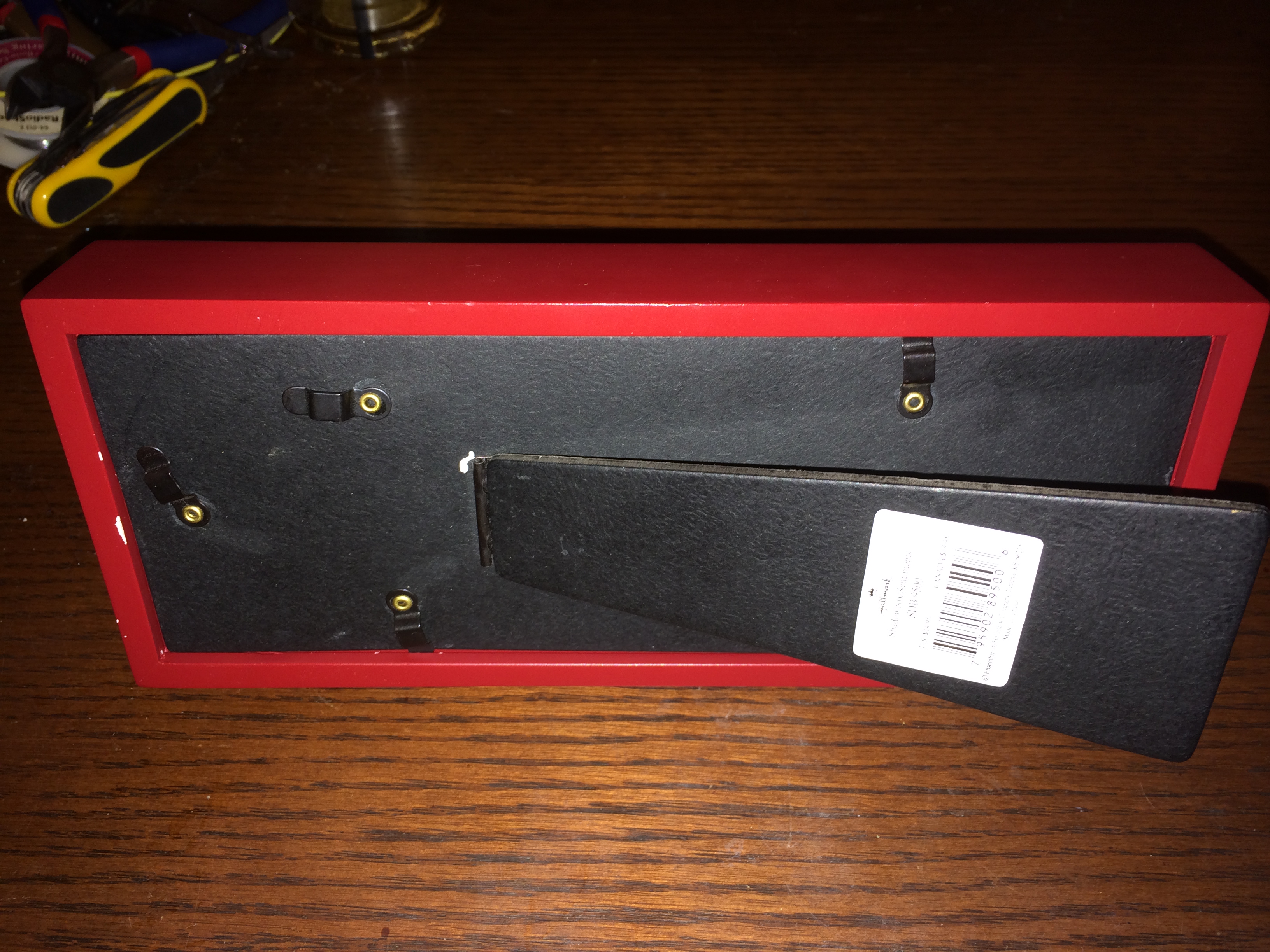
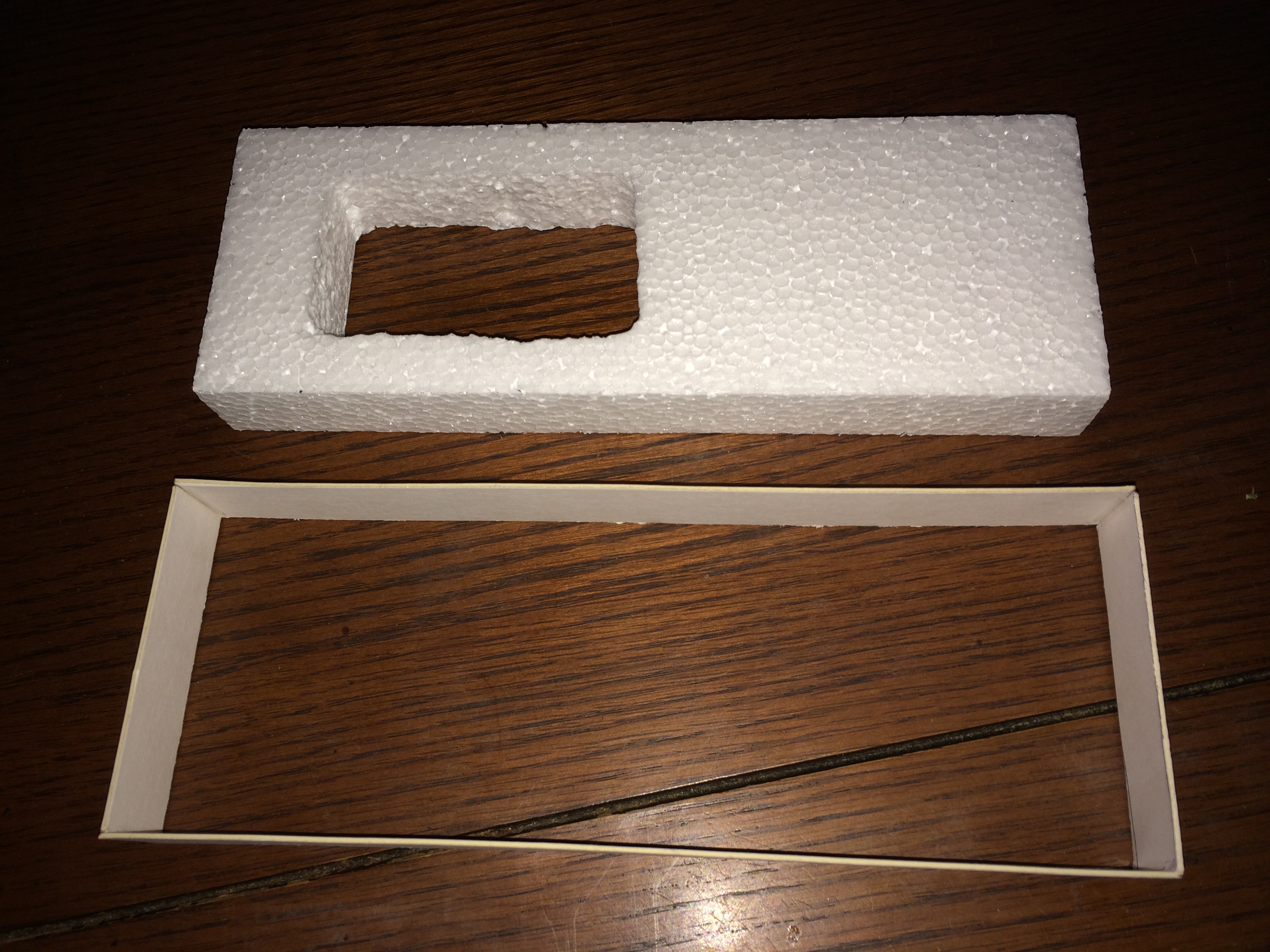
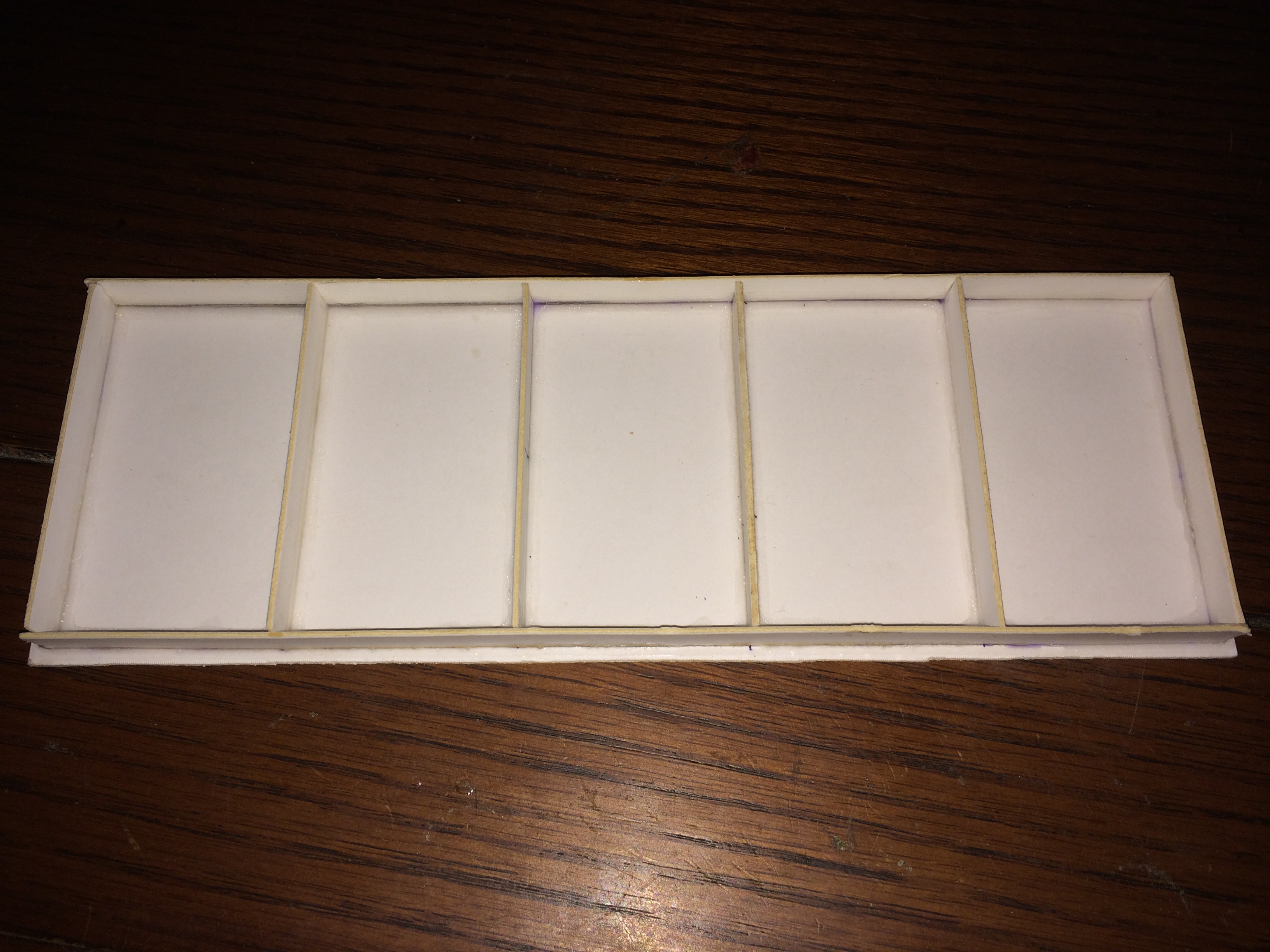
With the back off the frame we can see that there is a large piece of styrofoam that occupies the remaining space in the frame and helps push the picture and glass towards the front while providing pressure to the rear plate. Finally with all of the parts out of the frame we can see the amount of space to work with will be quite confined but still possible to work within.
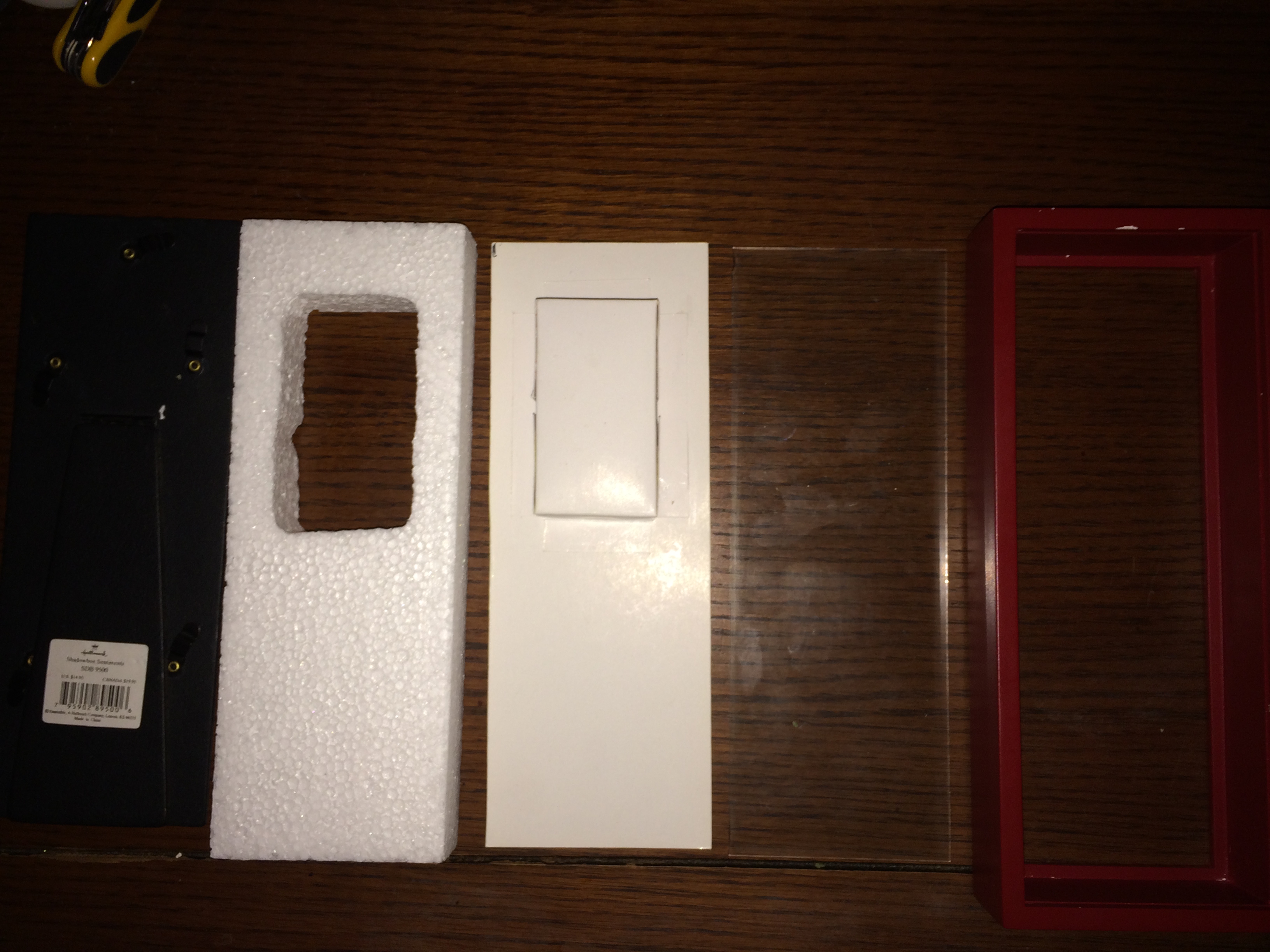
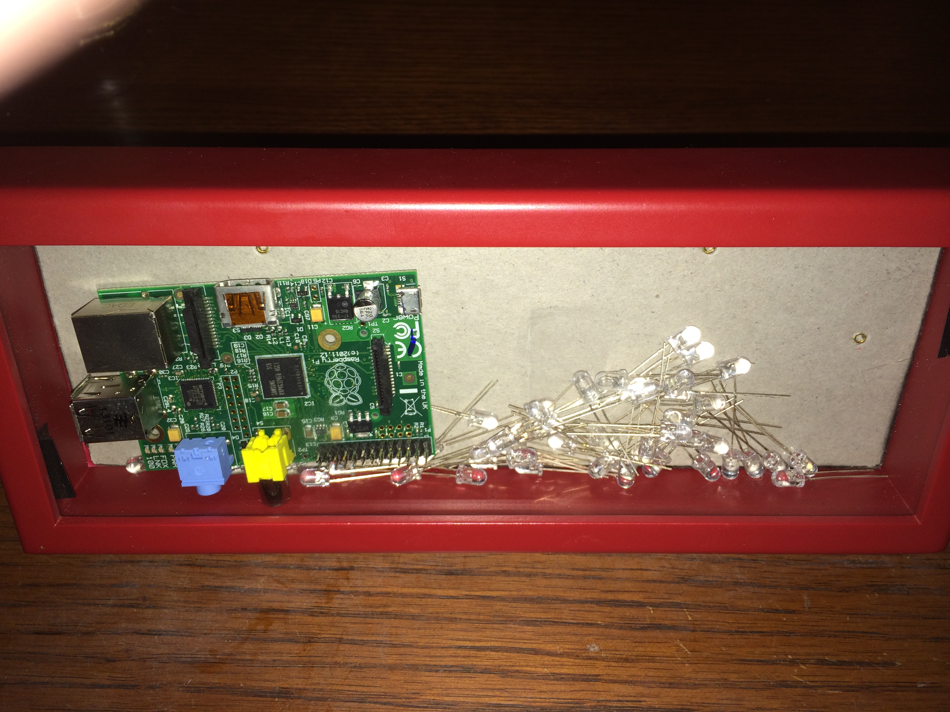
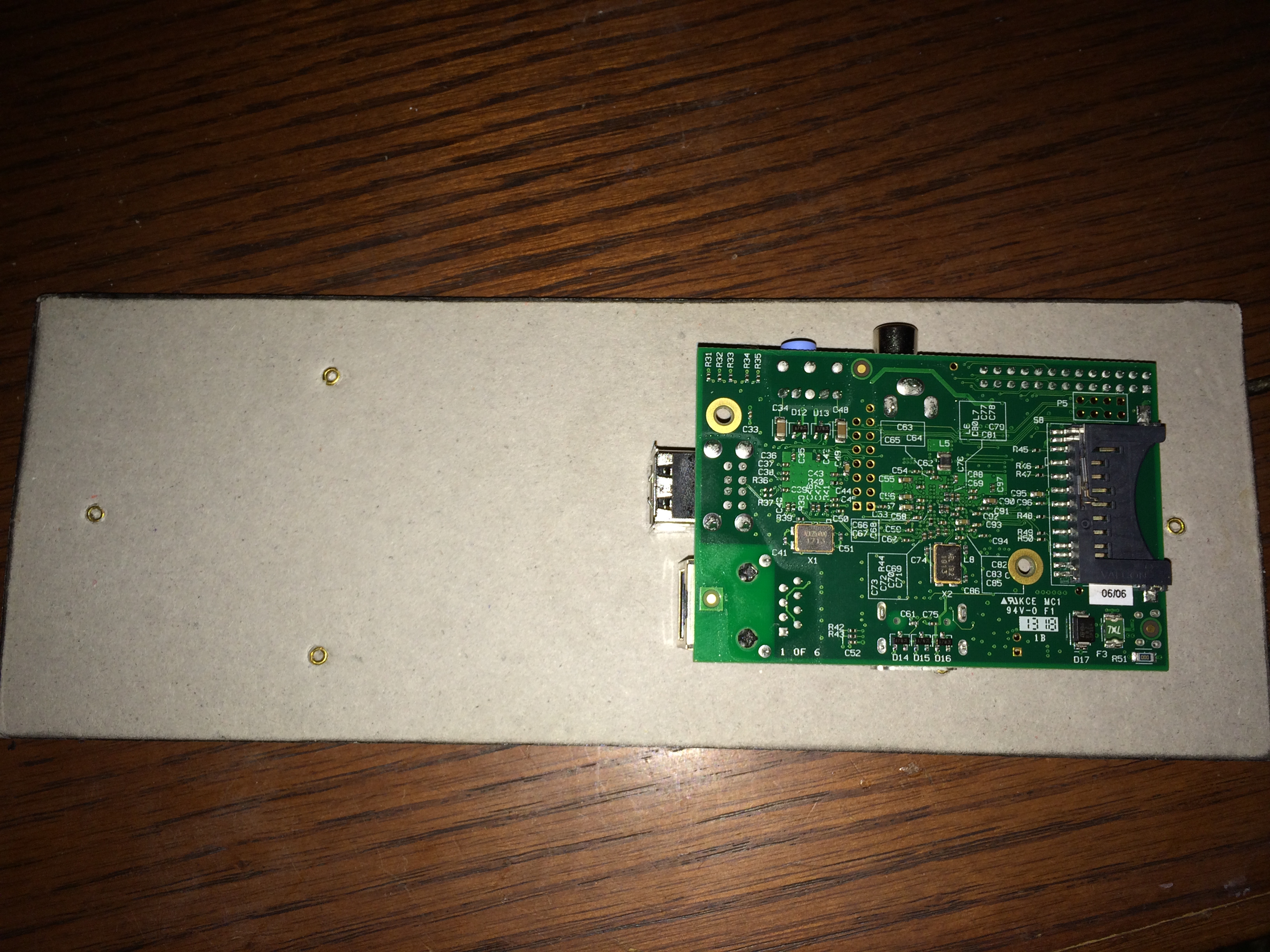
With all the parts outside the frame the RaspberryPi and an assortment of LEDs were placed inside the frame just to get a visual for how much room there will be on the inside once the back is sealed up.
Design
With a frame selected it was then necessary to create some numbering in your favorite drawing program in this case I used Photoshop but anything that supports transparency will work with layers being an added bonus. I wanted to come up with a design similar to the one used in WarGames but the point was not to try and replicate that sign exactly.
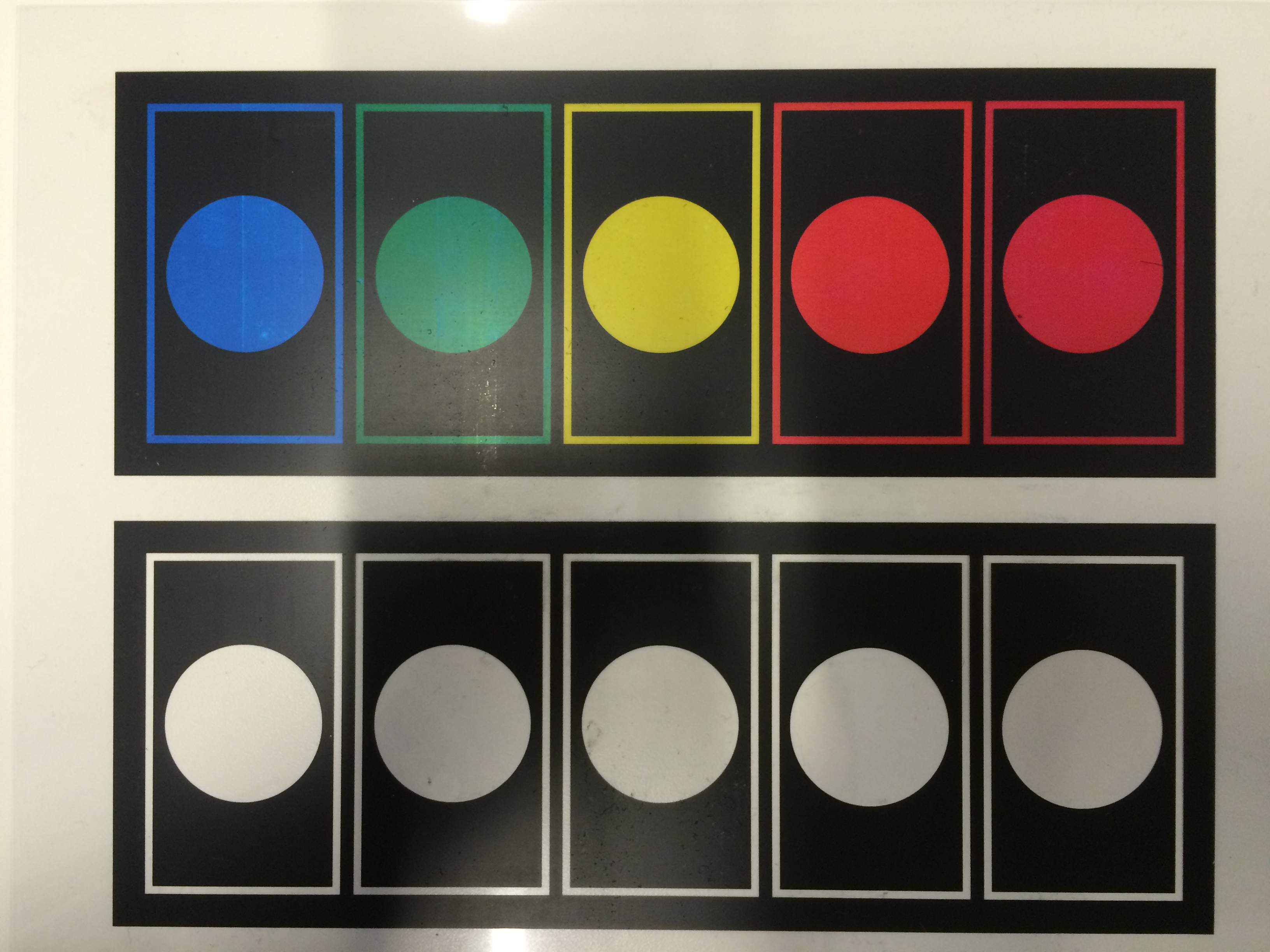
The images below represent the dimensions of the frame with its border shown in red, the white lines indicate the internal framing that will need to be done to prevent light leakage between the various numbers. When printed on transparency film only the black and colored area where the number and its border are will be shown and then will be used as an overlay on top of the individual number cells.

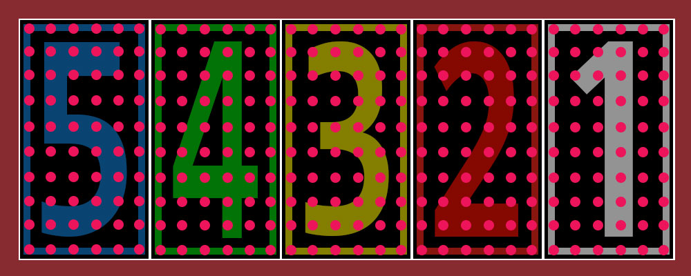
The first shows the basic design and numbering of the overlay that will be printed and cut to shape. The second image shows the pattern of the LEDs that will light the individual number cells. There are 60 LEDs per digit with a total of 300 LEDs making up the entire display.
Project Skeleton
Projects are generally built one of two ways that differ in the way the internal components are attached to the body and to each other. I personally prefer to build a sort of inner skeleton or frame that the major components will attach to and is removable as a whole from the body. In this case I make use of thick poster board material to construct and attach the internal parts.
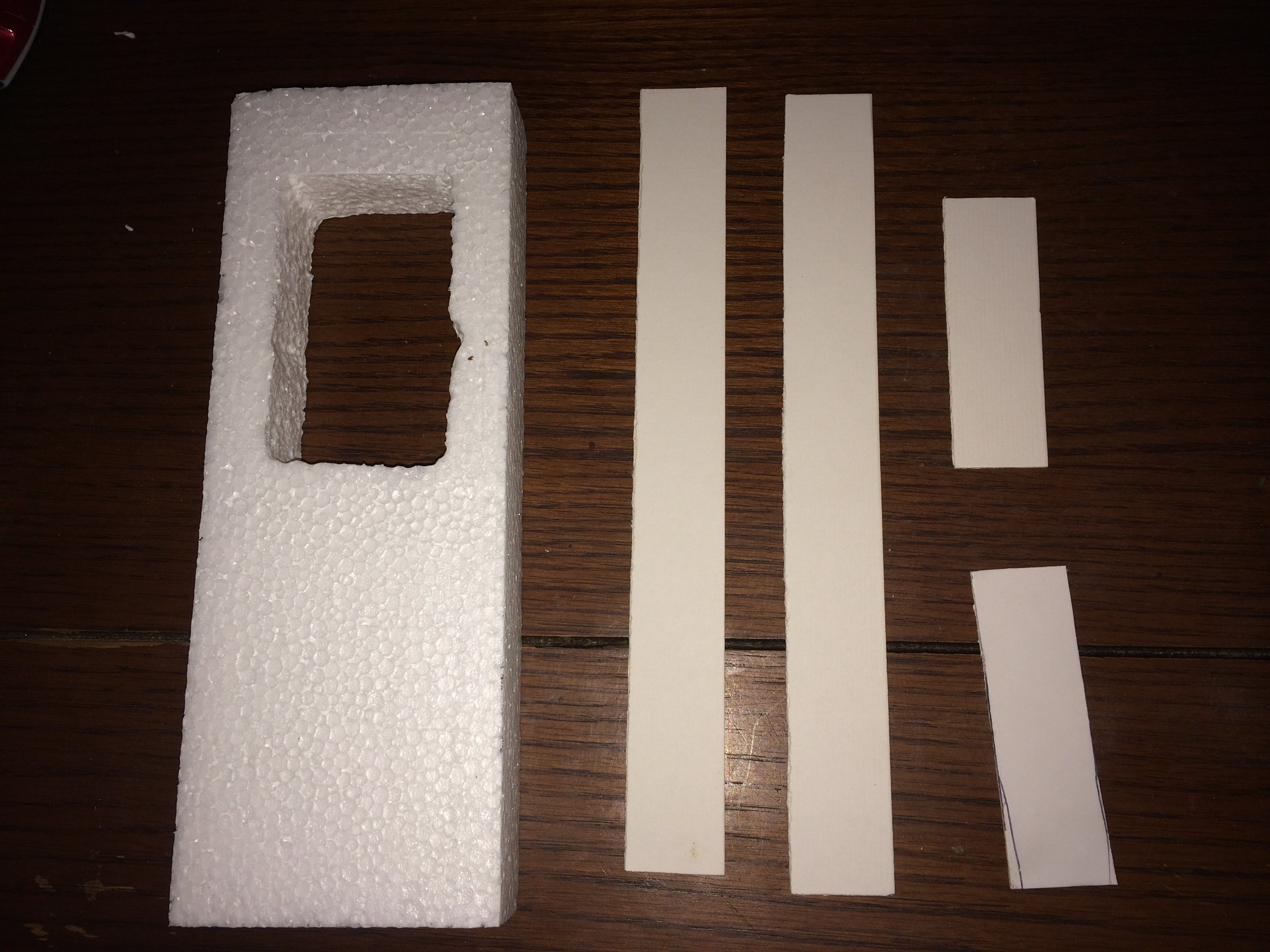
First a series of pieces were cut to the same general dimensions as the styrofoam that was removed earlier and then glued together with my super glue of choice. This frame will act as a spacer between the front piece of glass and the rear board and will be used as a basis for attaching the remaining bits.
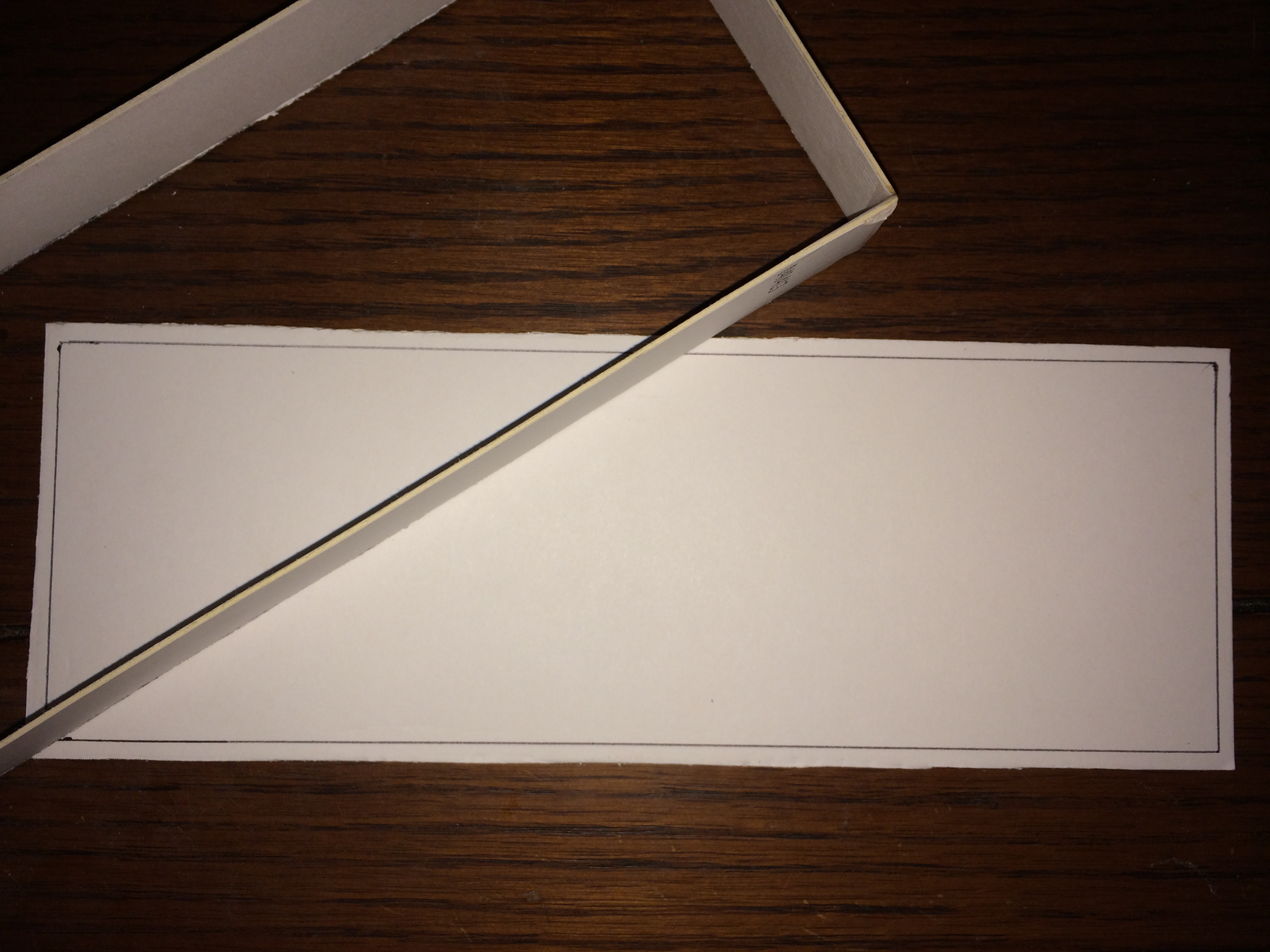
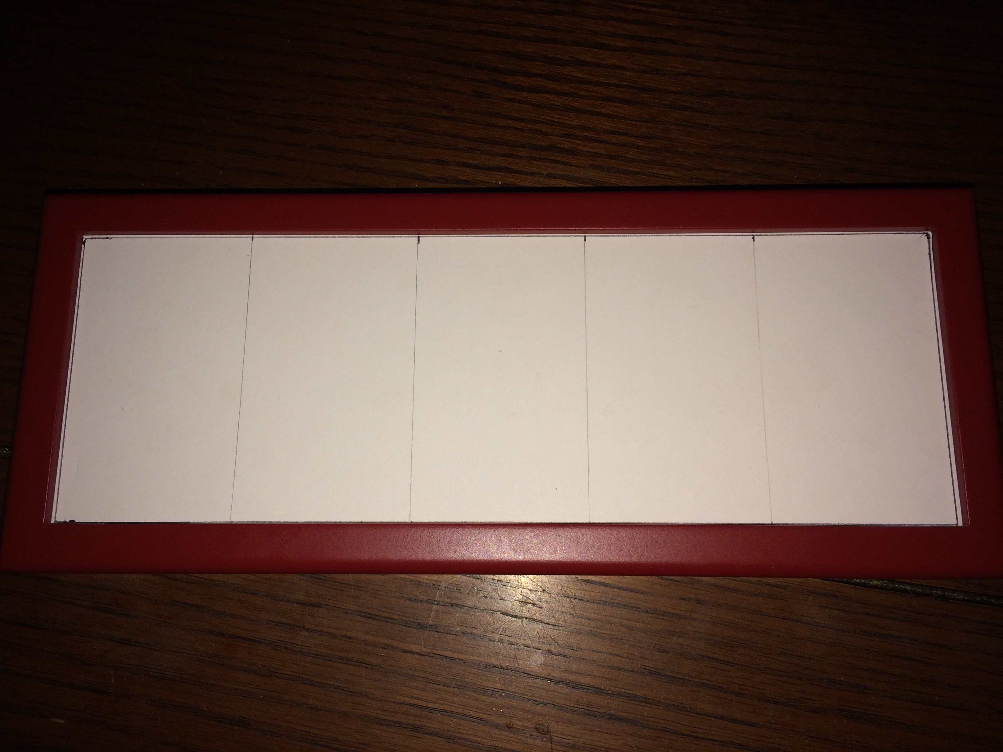
A piece was then cut that will fit inside the frame constructed above and is slightly smaller in length and width than the piece of styrofoam. With the piece cut and test fitted above I started to mark out the visible area for the individual digits that will make up the final defcon sign.
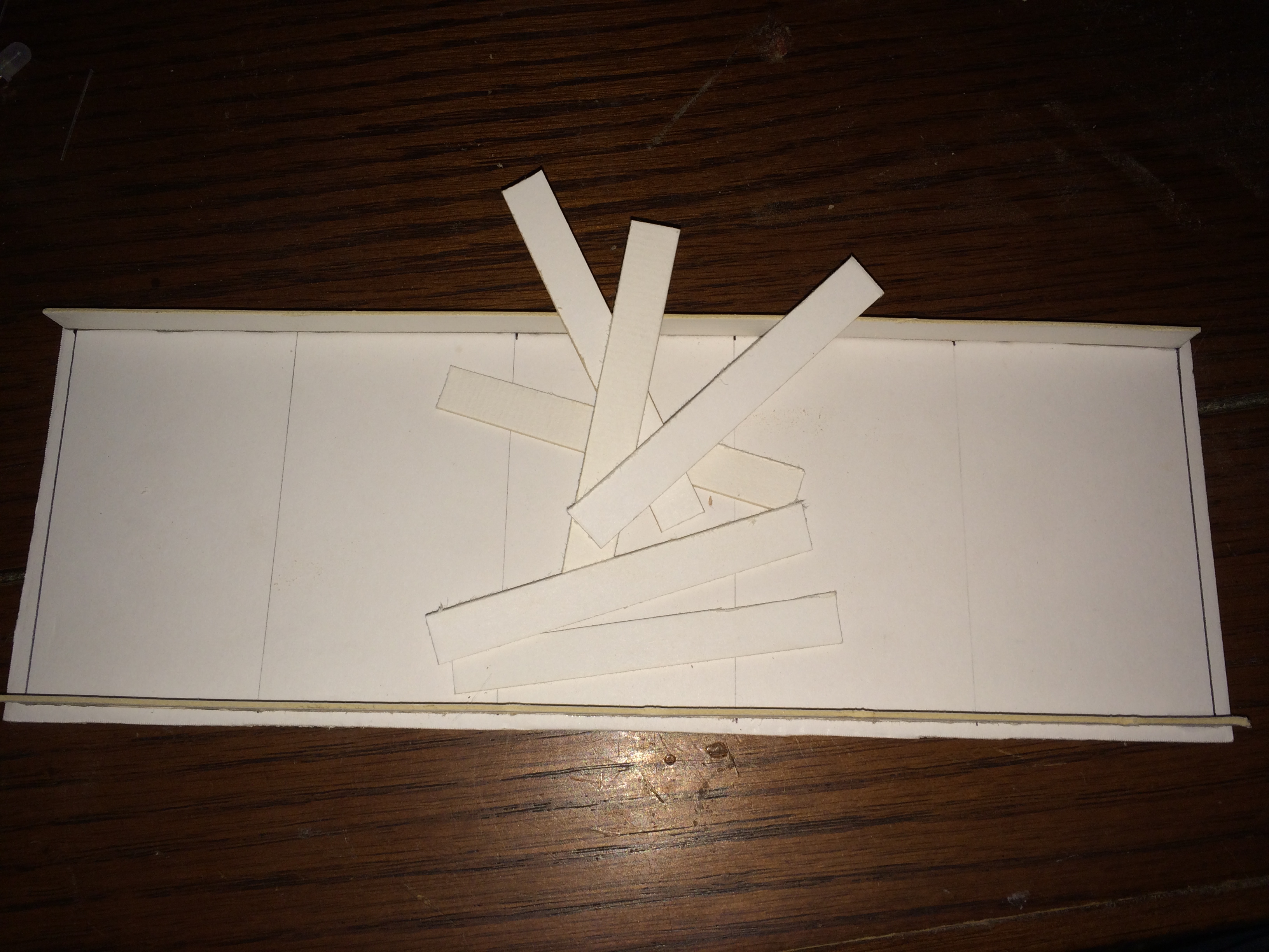
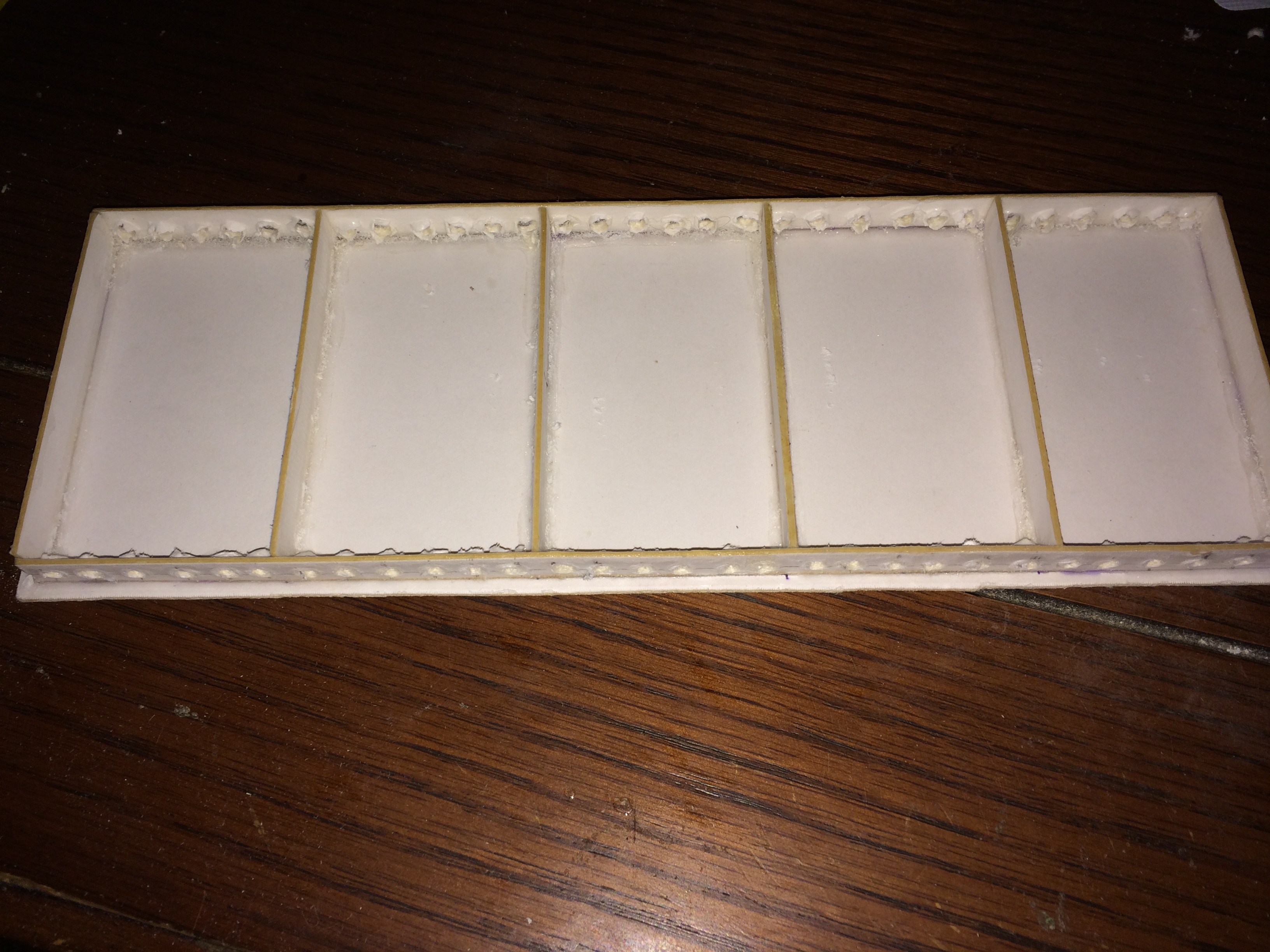
With the backing plate cut and marked to size it was then time to cut some strips to use as baffles or separators between the individual digits of the display.
Mounting the Raspberry Pi
For this project I have decided to mount the Raspberry Pi and the other control electronics to the rear plate and use a small 6 pin cable to link the display with the rear plate. First a few bits needed to be removed from the rear plate and a housing made to allow access to the various ports on the Pi.
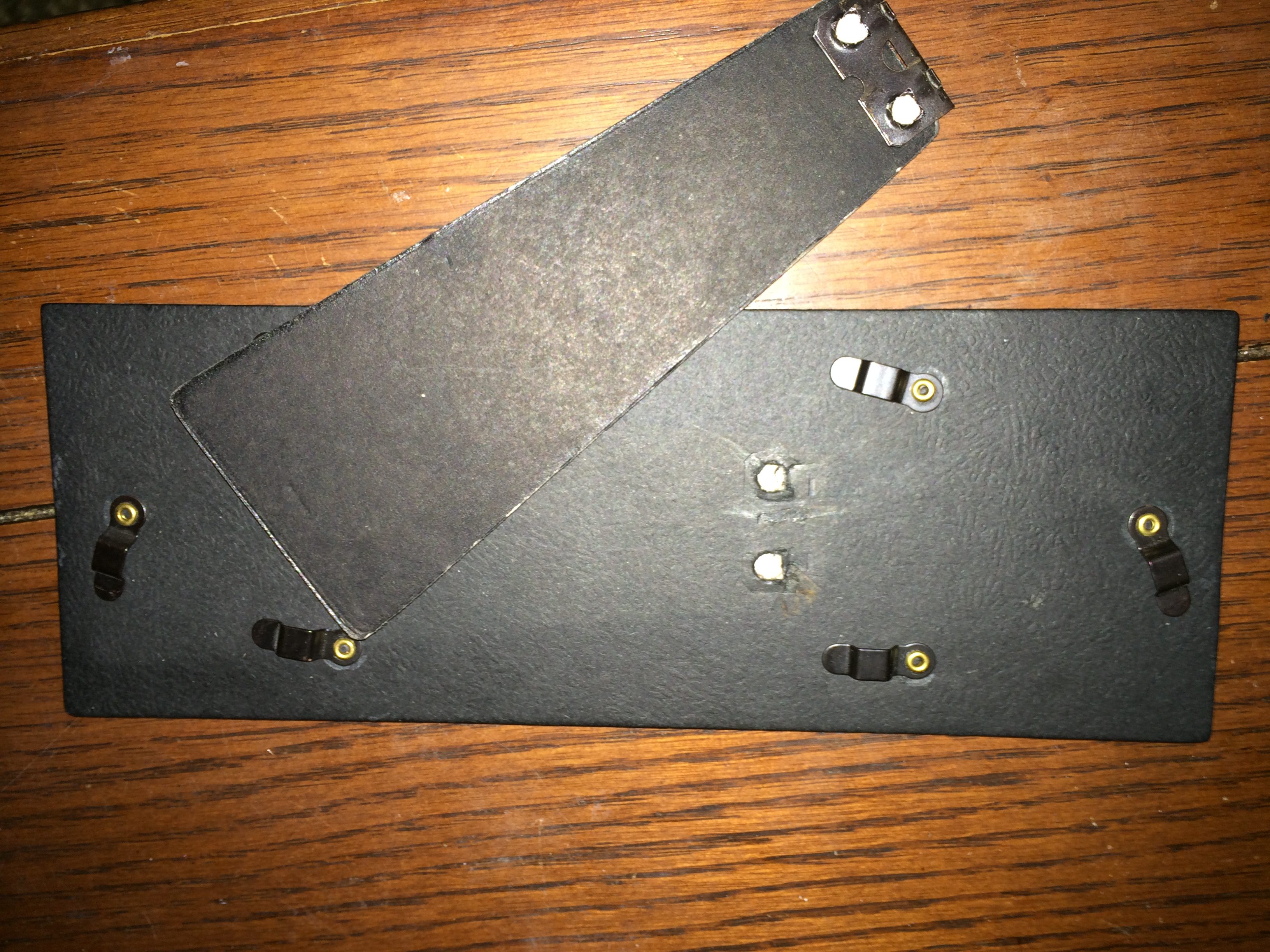
The stand on the rear plate needed to be removed as it is designed for a vertical orientation and this project will be mounted horizontally on a wall or placed on a flat surface. The stand is riveted in and did not come out easily but with a little patience I was able to avoid damaging the rear plate adversely.
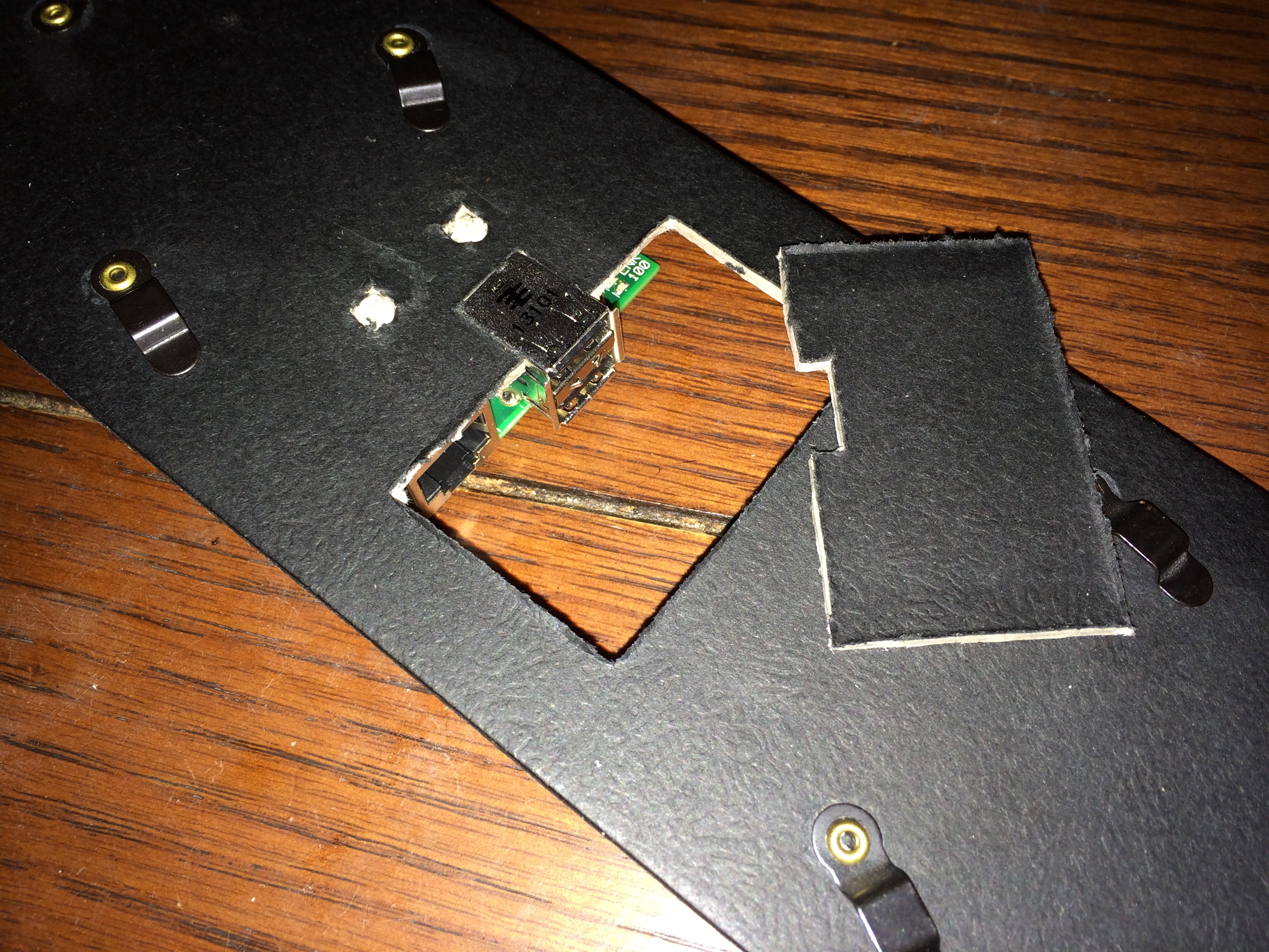
Although the only outside port the project will absolutely require will be a power input I thought it was important to expose the USB ports especially where the WiFi adapter is just in case this needs to be switched out or removed for some reason. Additionally it is possible that when installed the project will require an ethernet connection so this port was exposed as well.
The first step was to pick a location and cut out a hole in the rear plate that would be large enough to accommodate the power connector, usb ports, and ethernet with a small bit of room to work with. It was important to keep this area as small as possible to ensure there would be room on the other side of the frame to mount the transistor board.
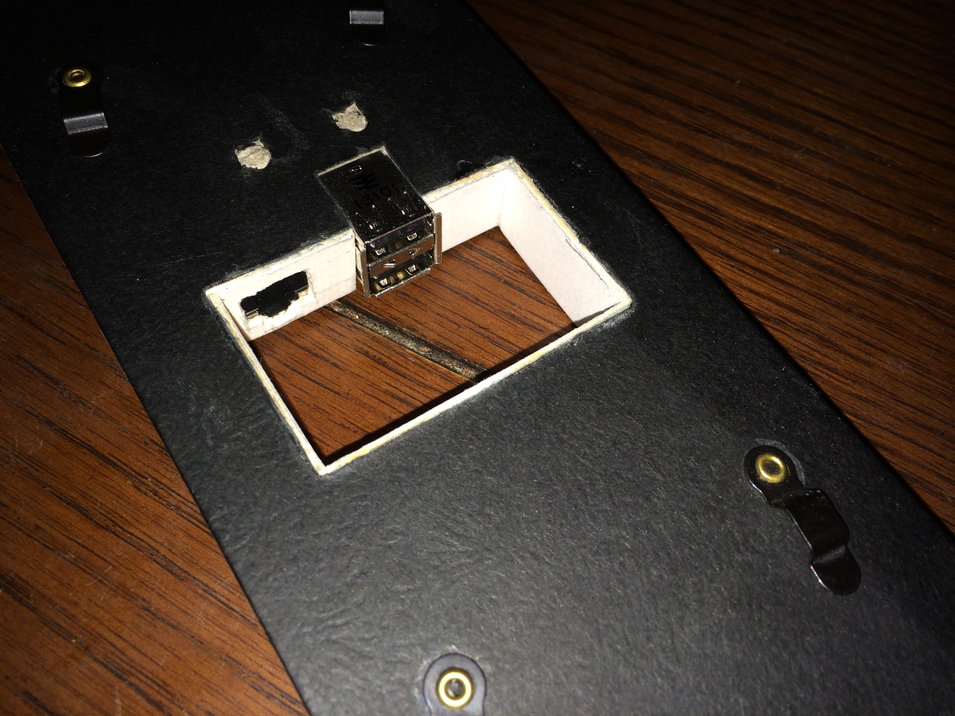
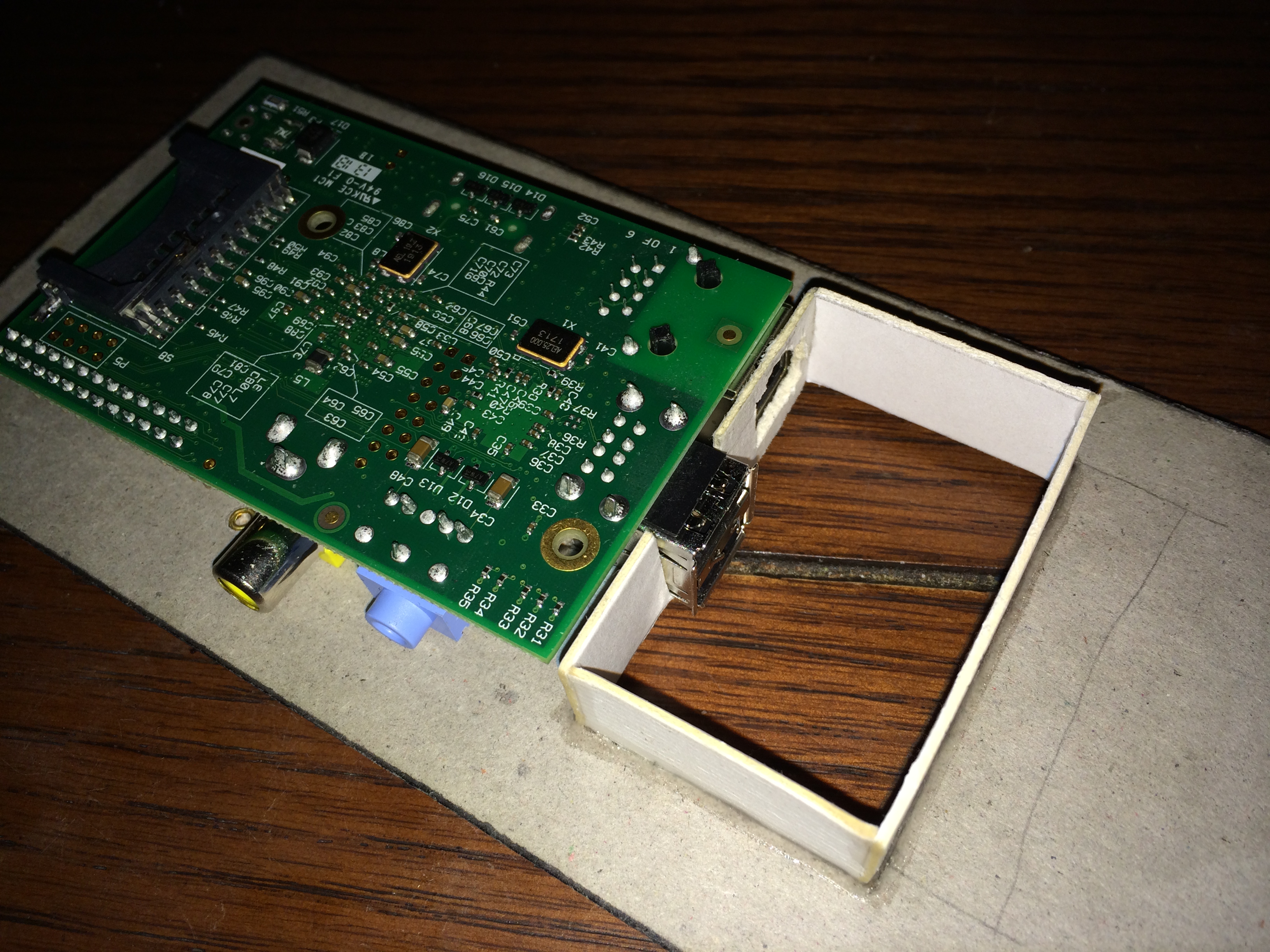
Next a small inner frame was constructed to fill the gap cut for the ports and to provide some rigidity back to the rear plate. This will ensure that fingers don’t make it to the inside of the project by accident and that wires inside don’t poke out of holes in the case.
Making stand-offs
The mark of a good modder is being able to look at a collection of pens and think to ones self that what we really have is a cup full of customizable stand-offs.
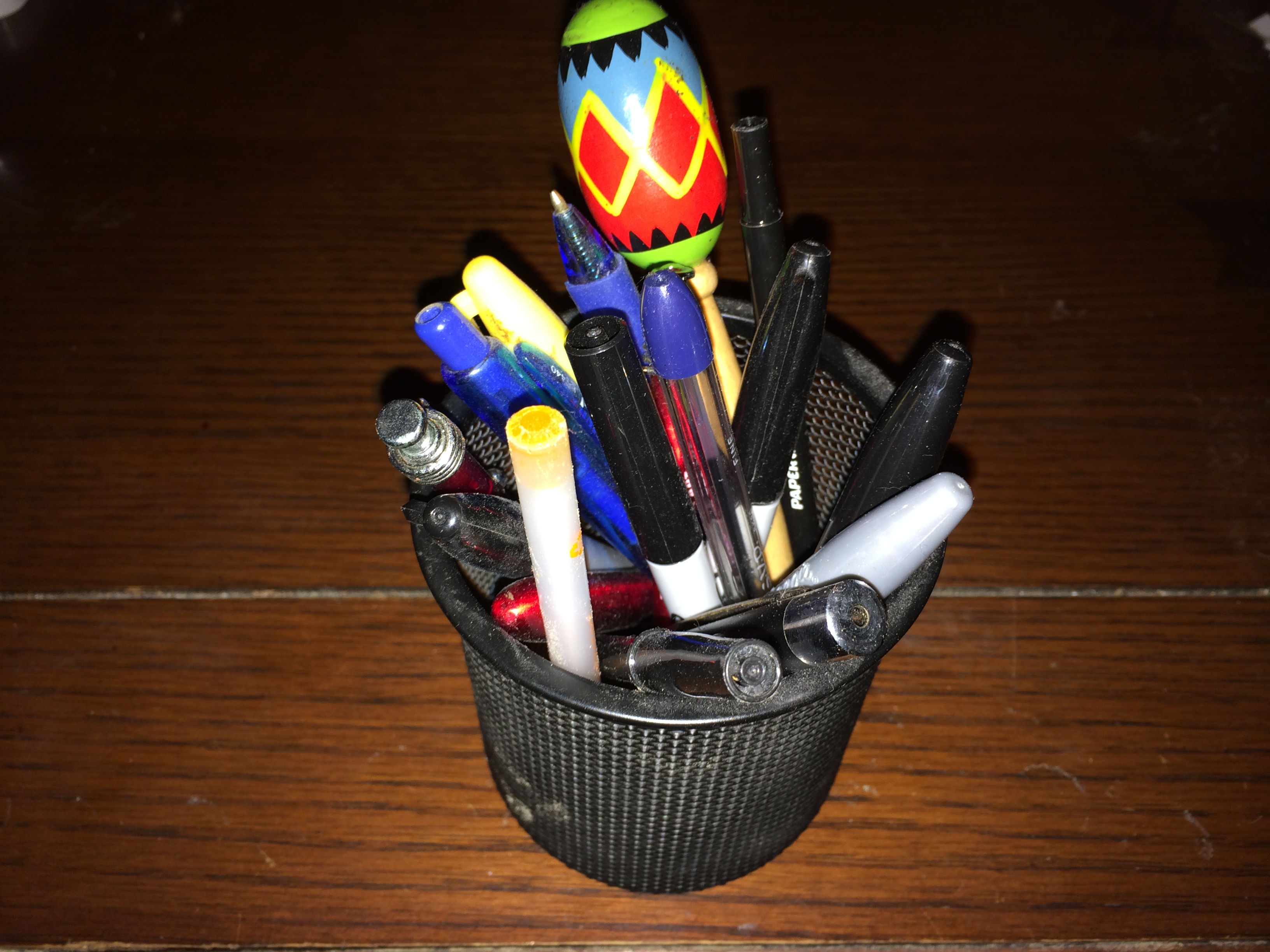
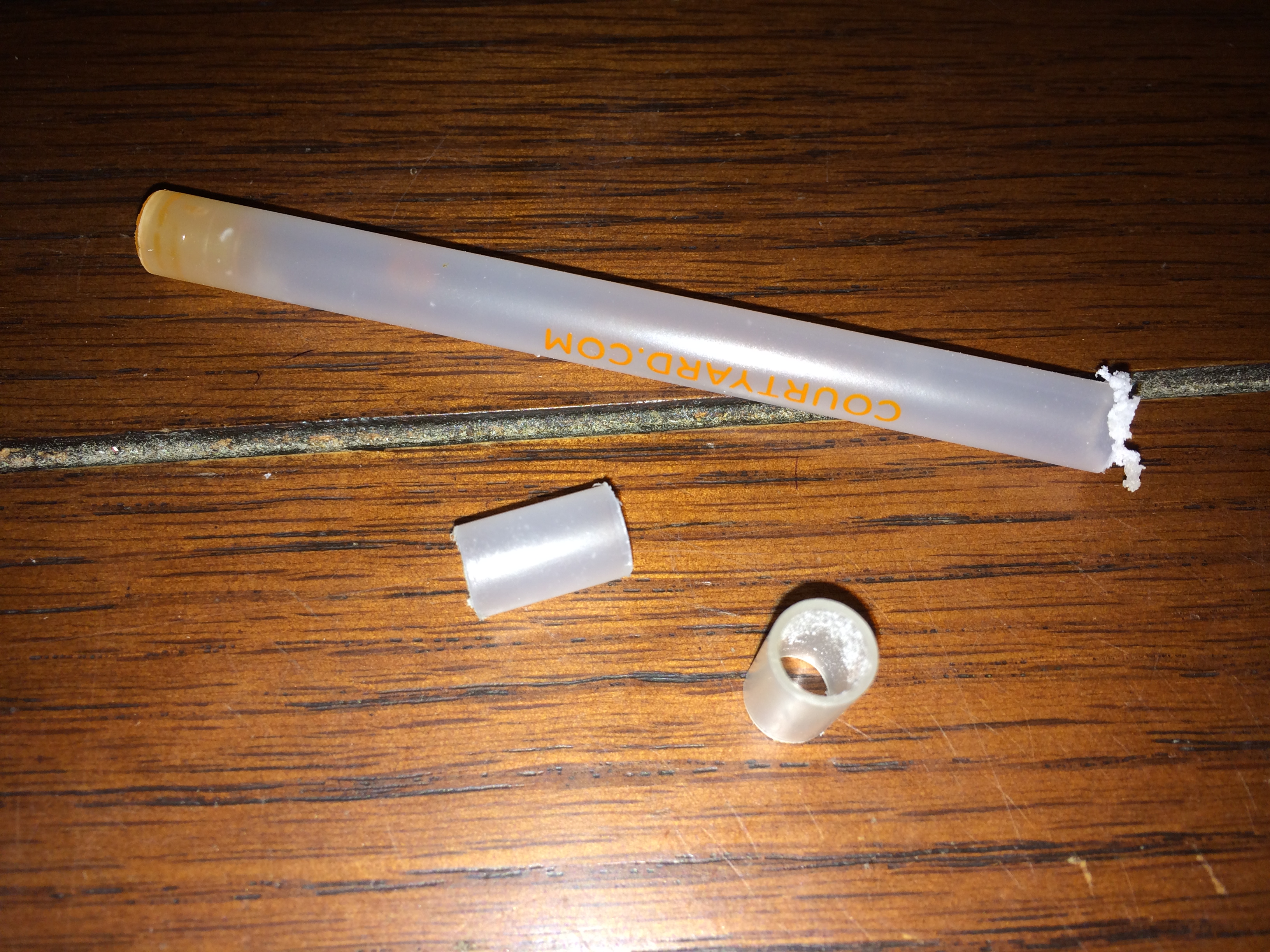
Picking out a classic BIC style pen I first removed the ink cartridge and eye measured some stand-offs to mount the Raspberry Pi to the rear plate.
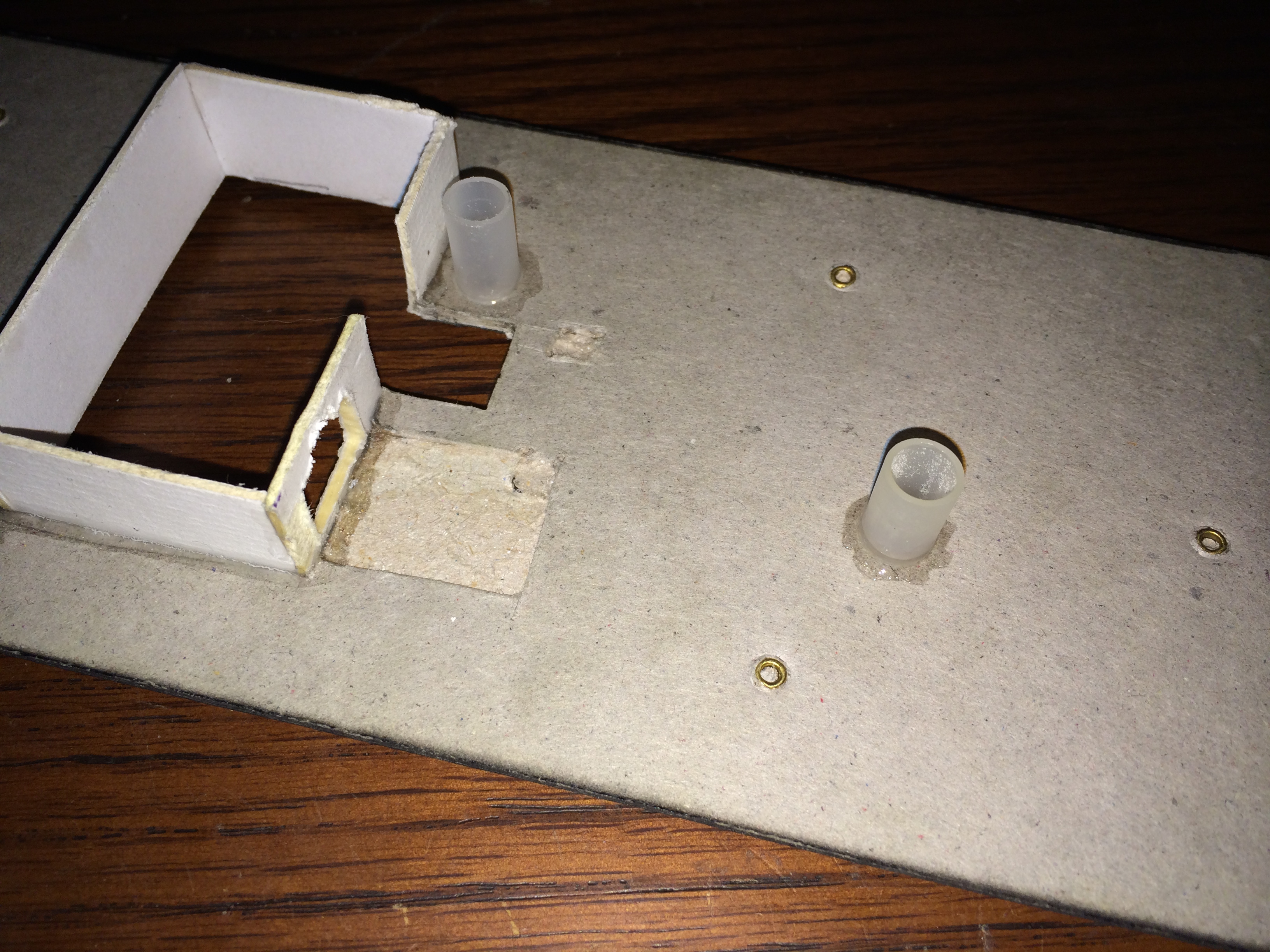
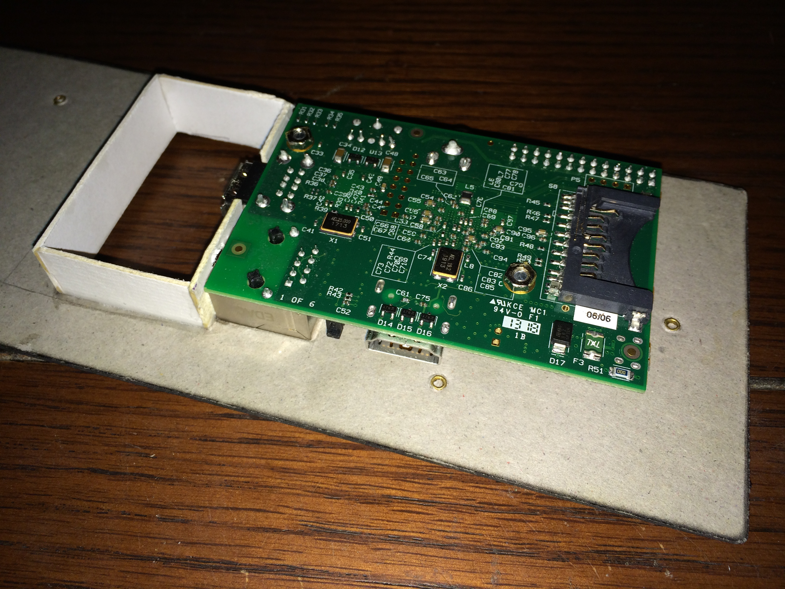
With the stand-offs placed in the proper locations they are then glued in place to ensure proper alignment as the Raspberry Pi is added/removed during the development phase of the project. Lastly the Pi is bolted to the rear plate.
LED Display
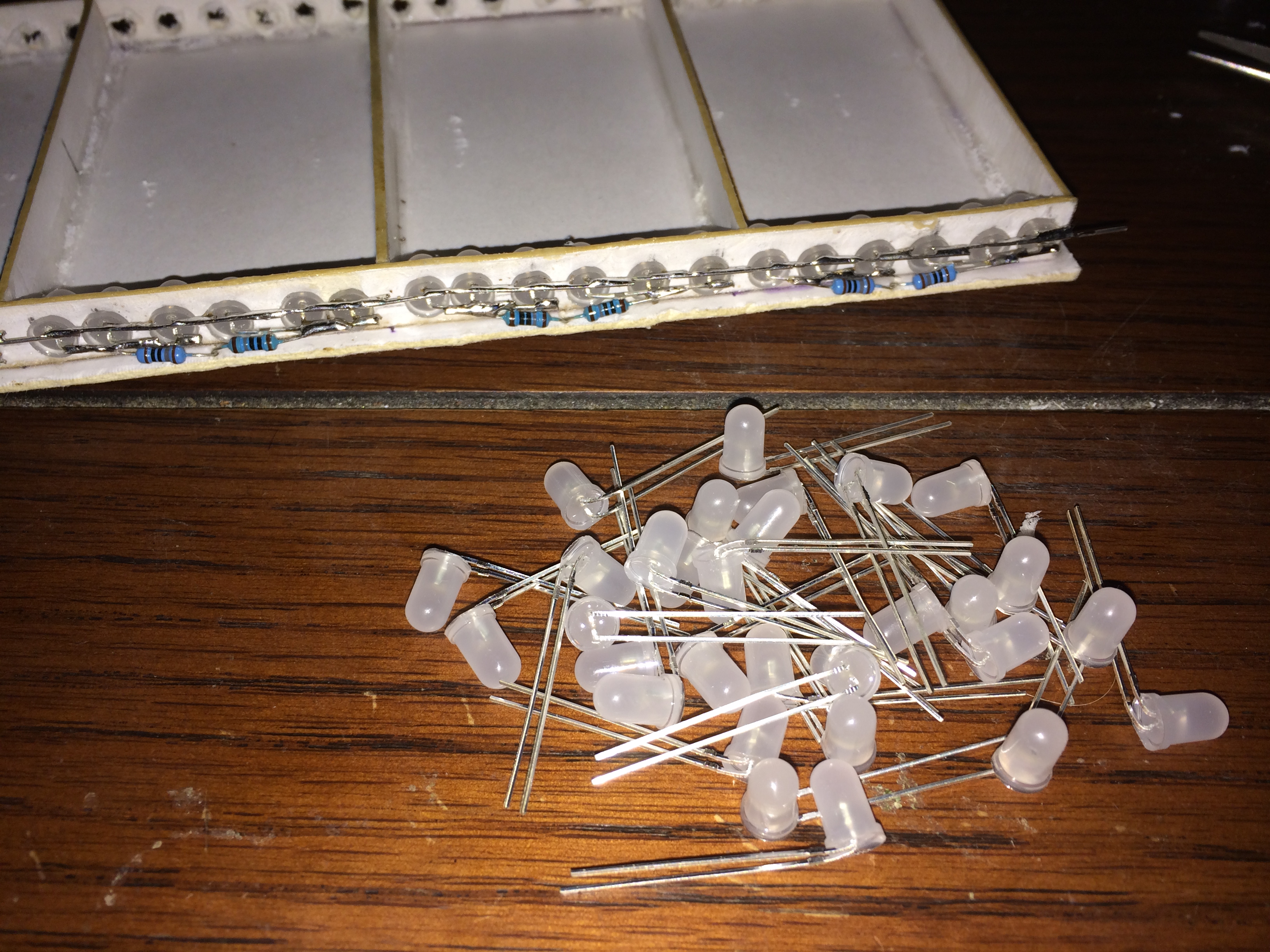
It was now time to construct the LED display that will be used to illuminate the digits of the Defcon sign, originally I was going to have a grid of 6 x 10 LED’s for each digit but it quickly became apparent that space was more limited inside than previously anticipated. As a compromise I discovered it would be possible to illuminate the digits from the top and bottom and cut down the amount of LED’s by one fifth from 300 to just 60 in total.
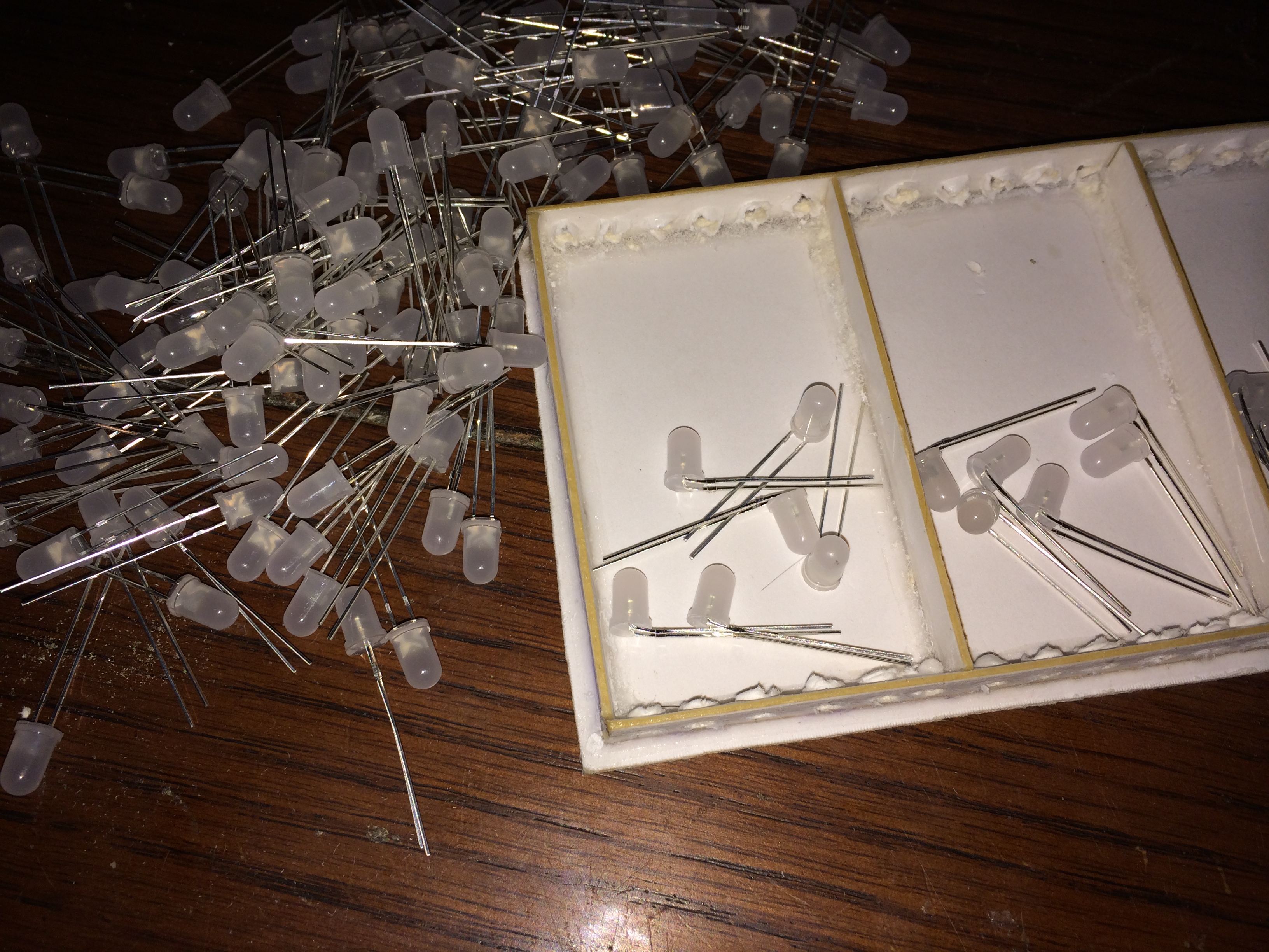
With the holes marked they were then drilled out using a bit that is slightly smaller than a normal LED so that once inserted the LED would stay in place with friction.
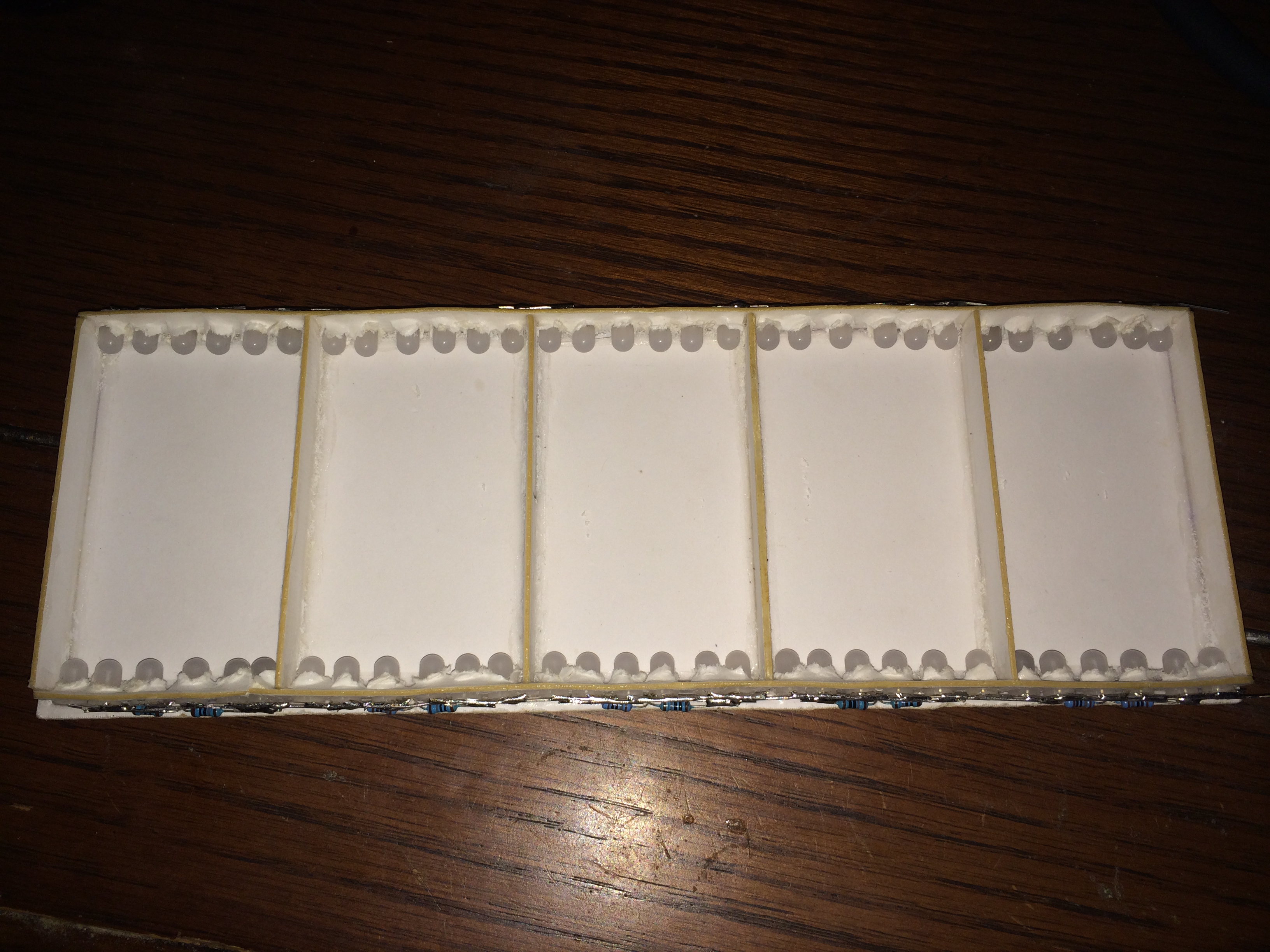
The LED’s are then arranged with their two pins all facing the same direction and soldered in a line connecting all the ground pins together on a single rail. The positive sides are grouped in sets of 3 and cuts down the amount of resistors needed by a third from 60 to just 10. Lastly the resistors are grouped in sets of two with each set representing either the top or bottom of a particular digit.
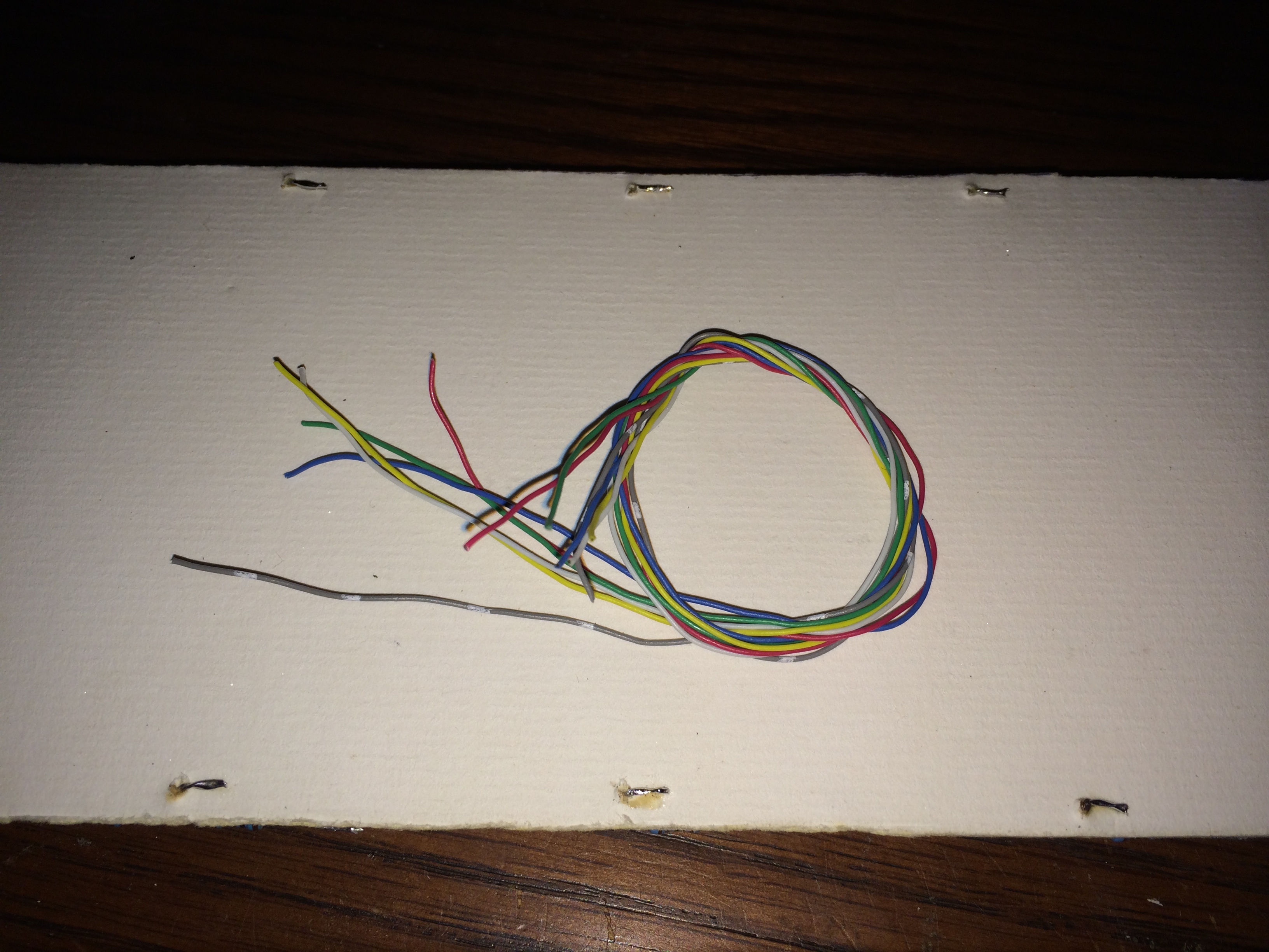

The resistors are then soldered on the rear side of the LED Display and wires attached that correspond to the color of the respective digit. The wire itself is salvaged from some old parallel cable that contained 25 wires for each of the pins of a parallel port, this wire is great as it is small, easily soldered, and comes in a wide variety of colors.
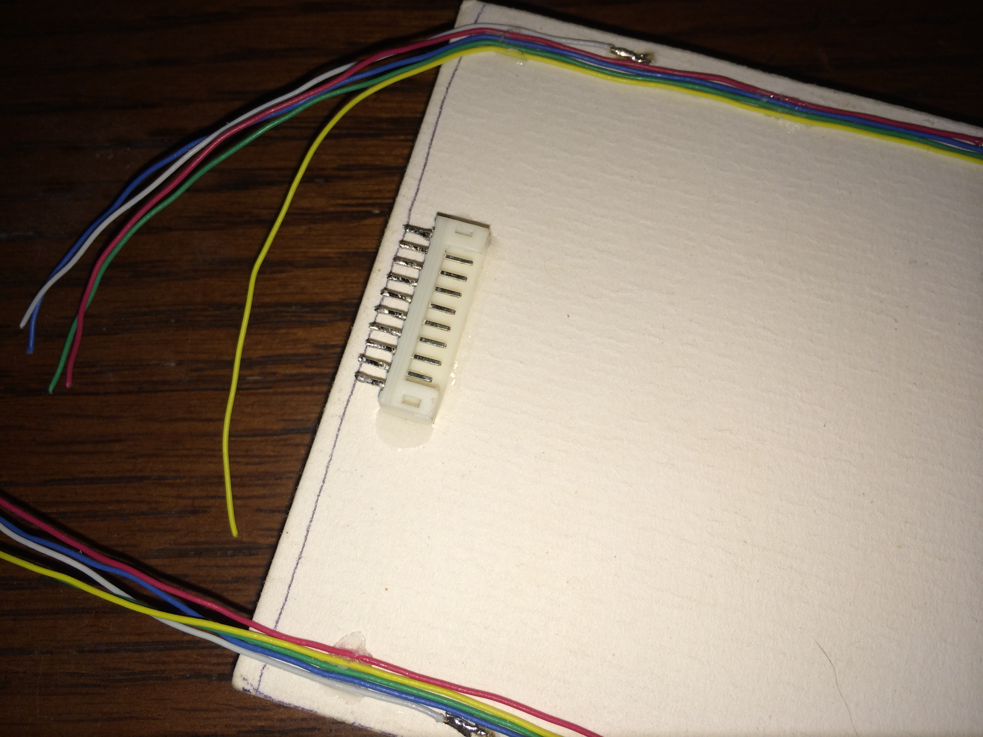
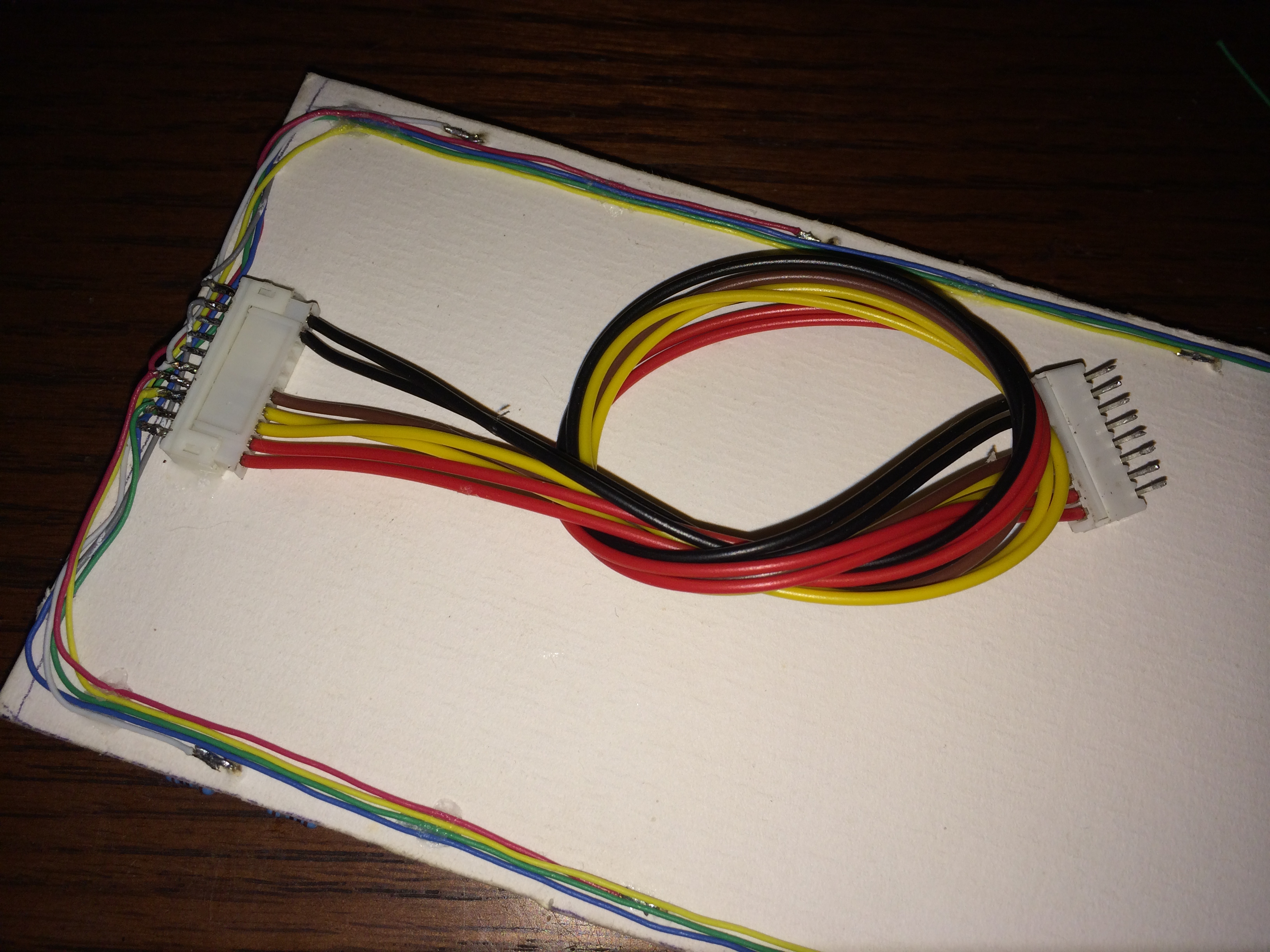
Lastly I found some wire with connectors on each end that would be suitable for the connection between the LED Display and the rear plate of the frame that will contain the Transistor Board. The connectors have a different number of pins ensuring the proper end of the cable is connected to its respective port and allows easy disassembly of the frame by not soldering the connections between the various boards and components in the Defcon sign.
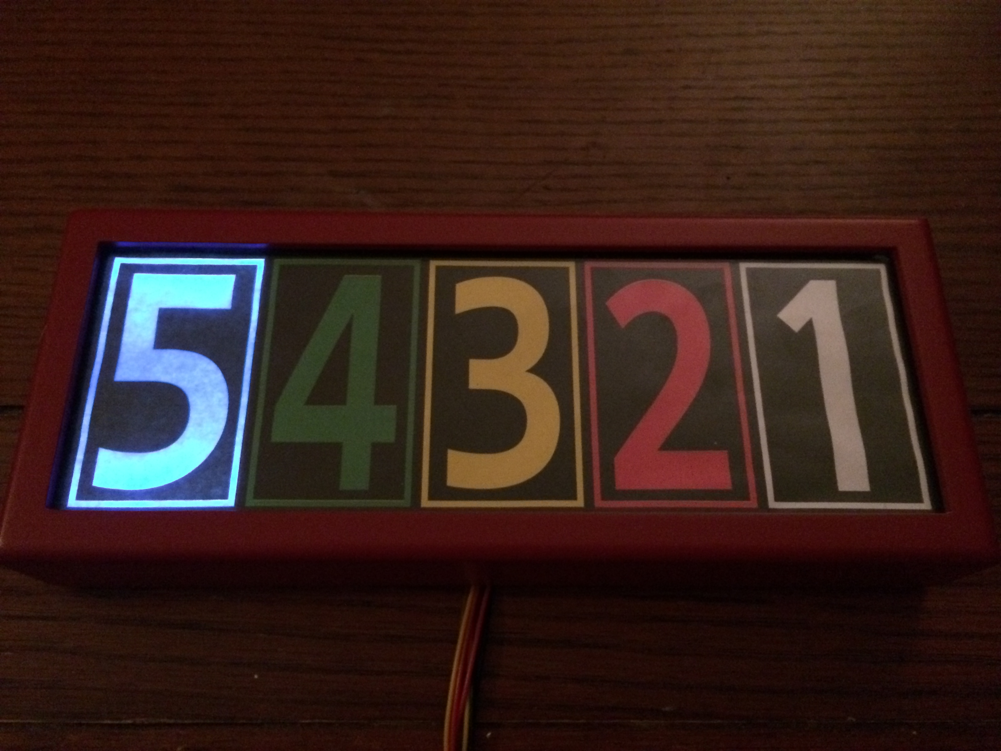
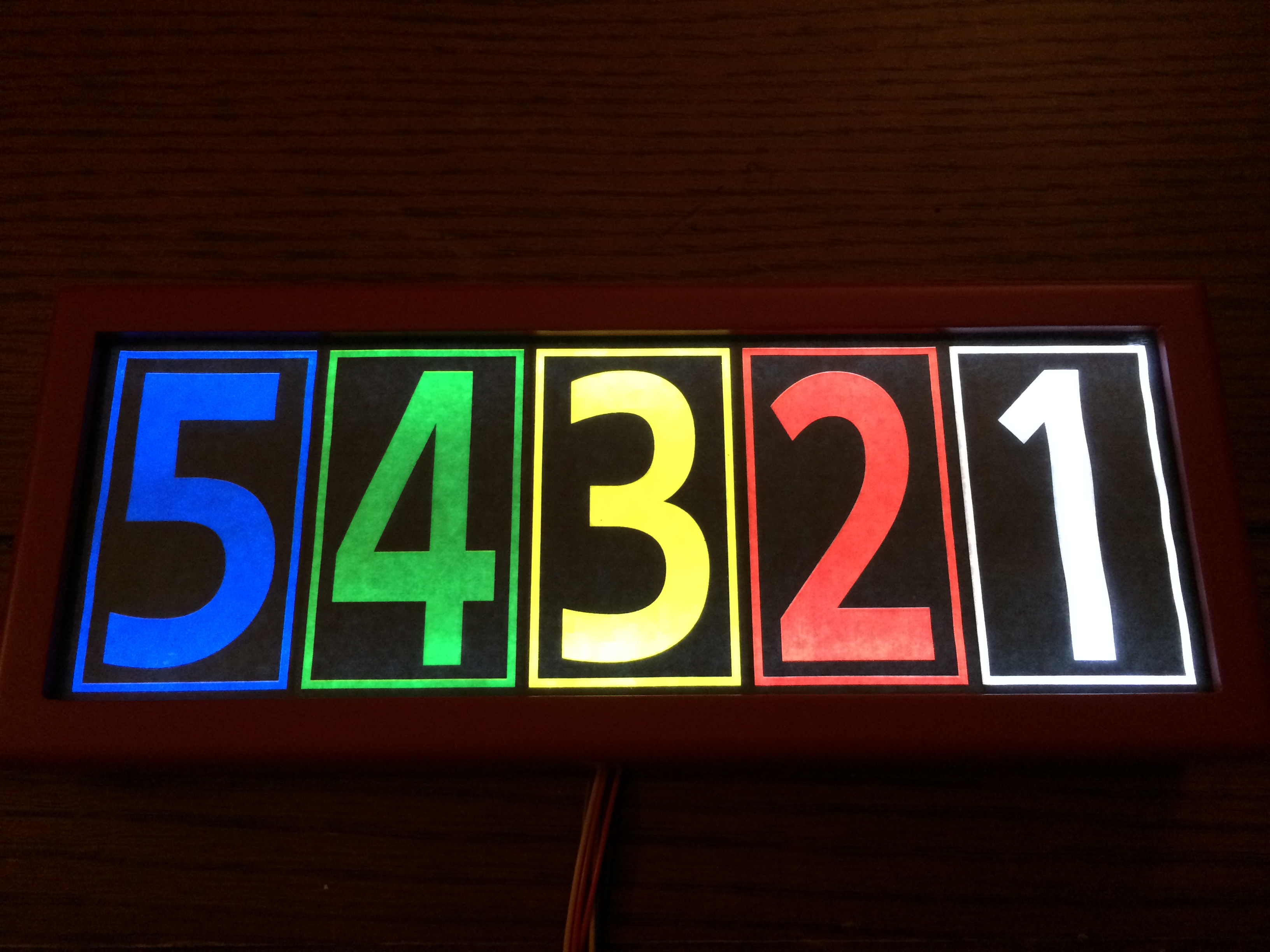
Using a printed sample of the final numbering overlay the LED digits were tested for dimensions, positioning, and light leakage between the numbers. The final overlay will be printed on transparency paper however, here I am using a low quality laser print of the overlay. The digits light up nearly as perfectly as if a much larger grid of LEDs had been used and diffuses quite well from top to bottom. The second picture is a better representation of how the colors look in real life.
Transistor Board
The Raspberry Pi’s GPIO pins can drive an LED or two but controlling anything more substantial requires some sort of switching board that takes logic level signals and translates those into higher voltage and/or amperage signals. For this project something as large as relay would not be appropriate and so we find ourselves using an old digital stand-by, the transistor.

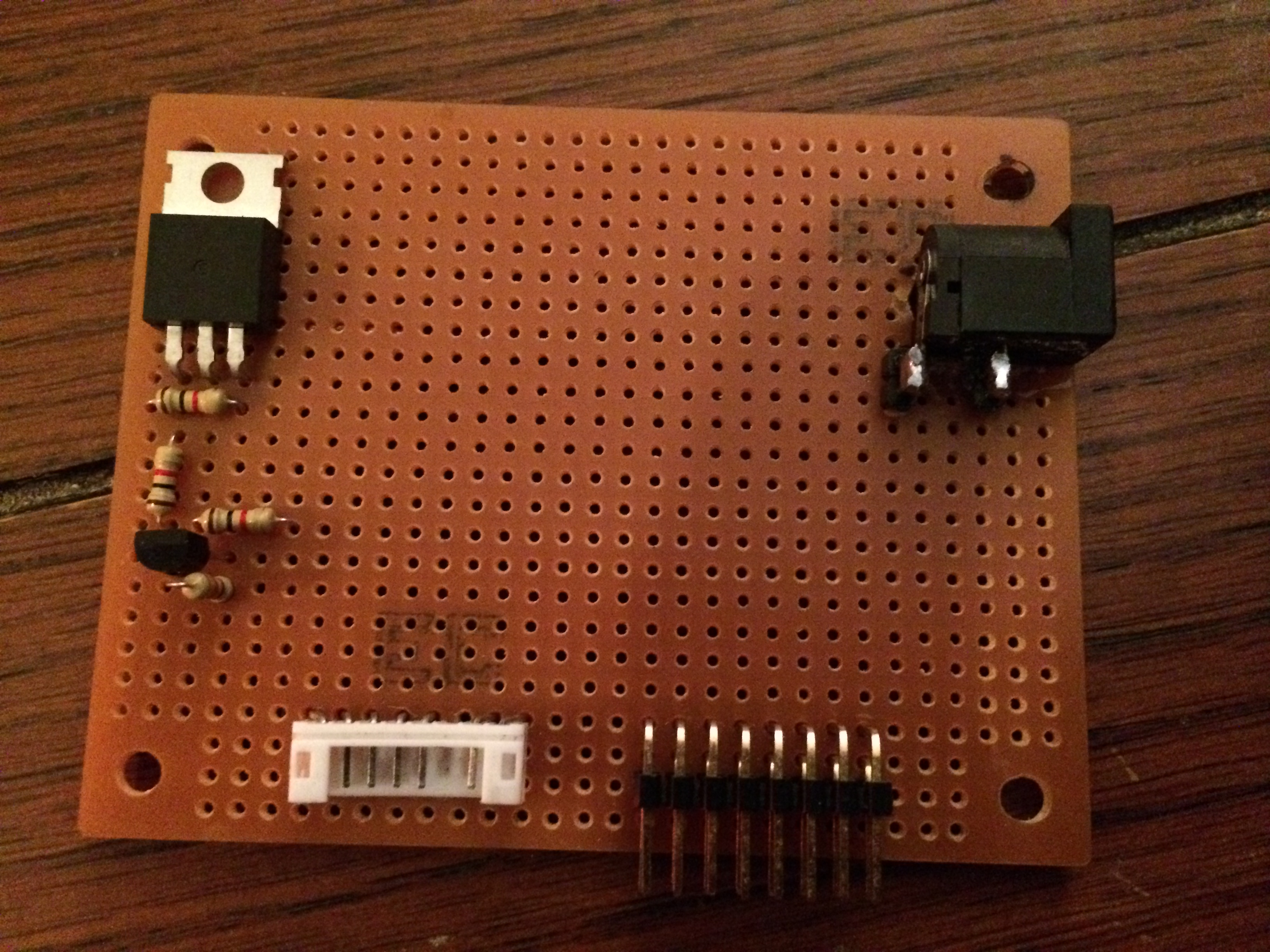
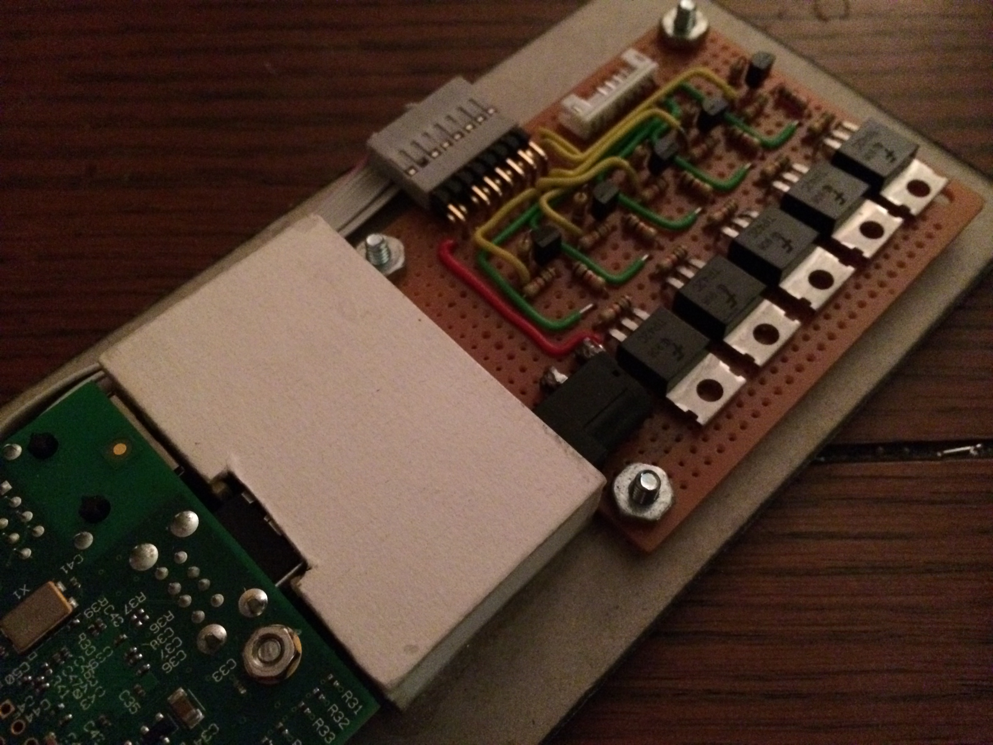
First on a piece of proto-board the necessary connectors are laid out and soldered. The barrel jack has been placed on its side and held in place with my super glue of choice to help align it properly for the I/O area on the rear plate. With the connectors ready I setup the first of five complementary transistor pair circuits that will amplify the logic level signals from the Pi’s GPIO pins.
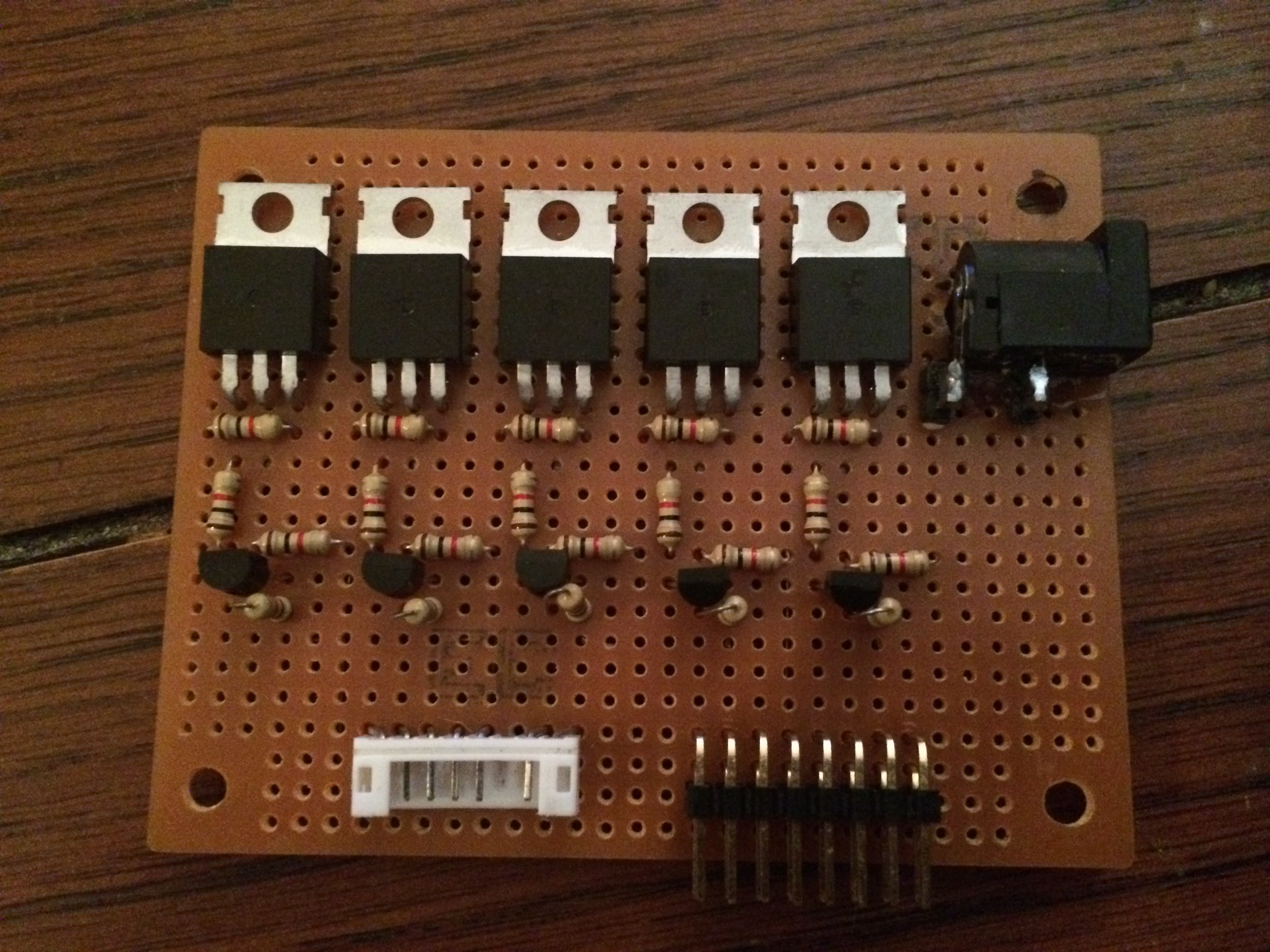
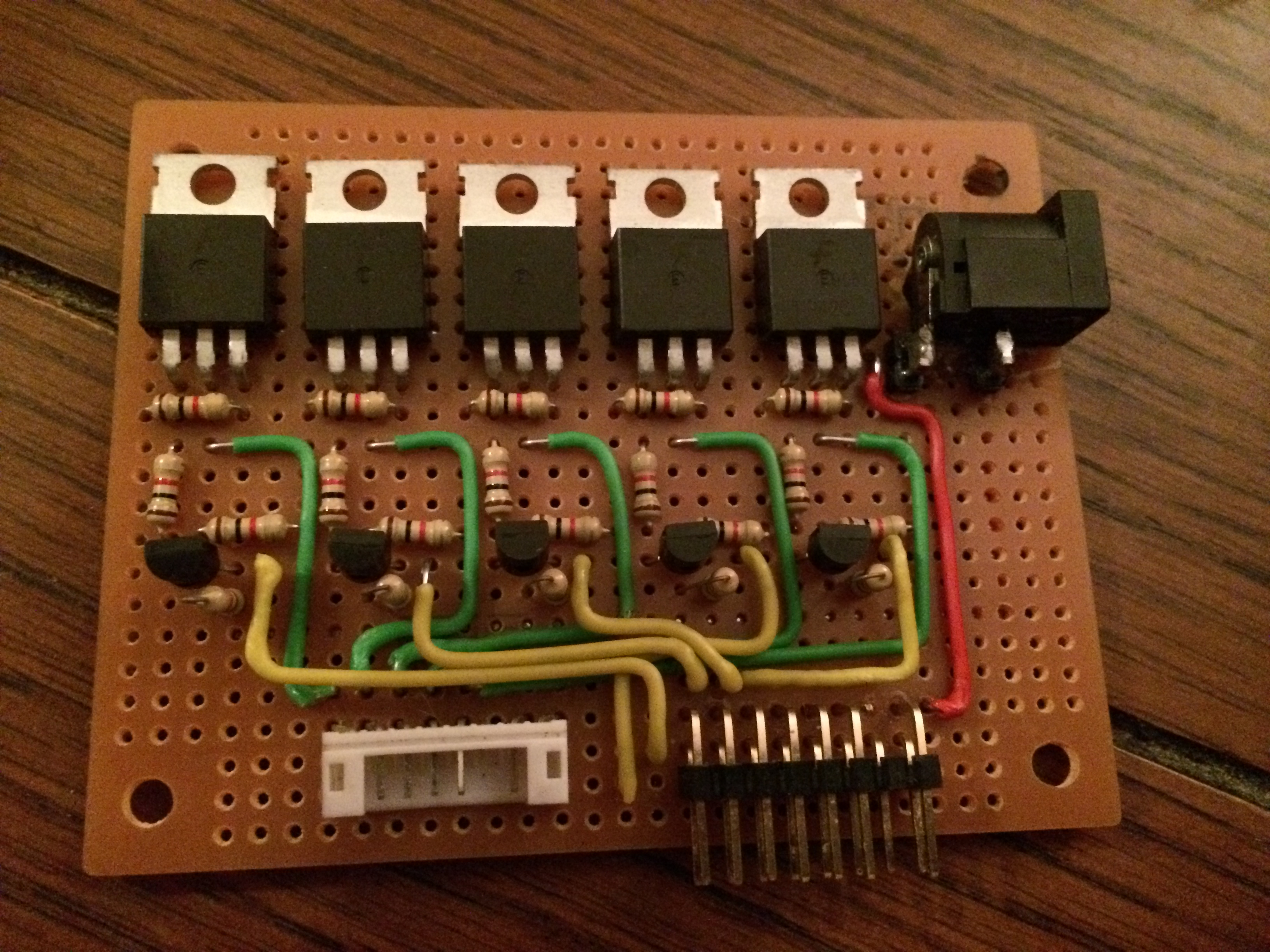
After testing the first transistor pair it was time to then add and solder up the remaining four sets of transistors. Once in place it was lastly time to connect the inputs and outputs of each pair respectively to their corresponding pins on the Raspberry Pi and LED Display connectors. The yellow wires are each of the inputs from the Raspberry Pi’s GPIO pins and the green wires connect to the outputs of the LED Display.
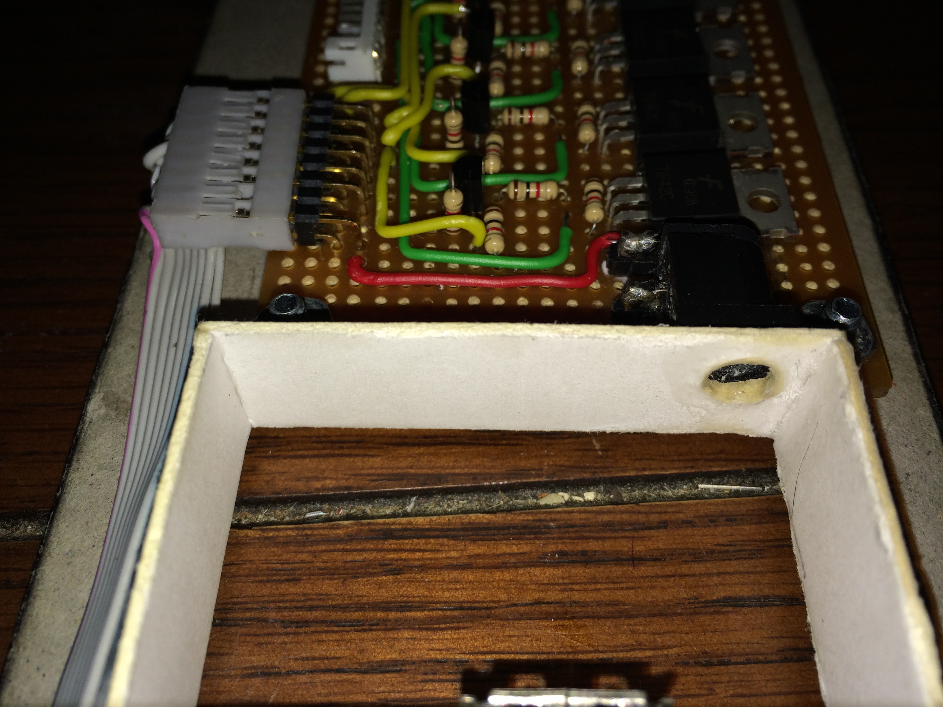
Lastly a small hole was cut in the I/O area to allow access to the DC barrel jack on the Transistor Board. With the last cut made in the I/O area a small piece of poster board was glued to seal up the outside from the inside of the project. The small gray cable provides the connection between the Raspberry Pi and the Transistor Board and supplies power to the Raspberry Pi while returning its GPIO signals back to the Transistor Board.
Ethernet Release
About halfway through mounting the Raspberry Pi it became obvious that if an ethernet cable was ever used it would be virtually impossible to remove the cable without wedging an object between the back of the I/O area and risking damage to both the Defcon Sign and/or the cable itself. Realizing the issue a simple lever solution was devised that would transfer the motion of pressing the clip on the ethernet cable to an alternate location.
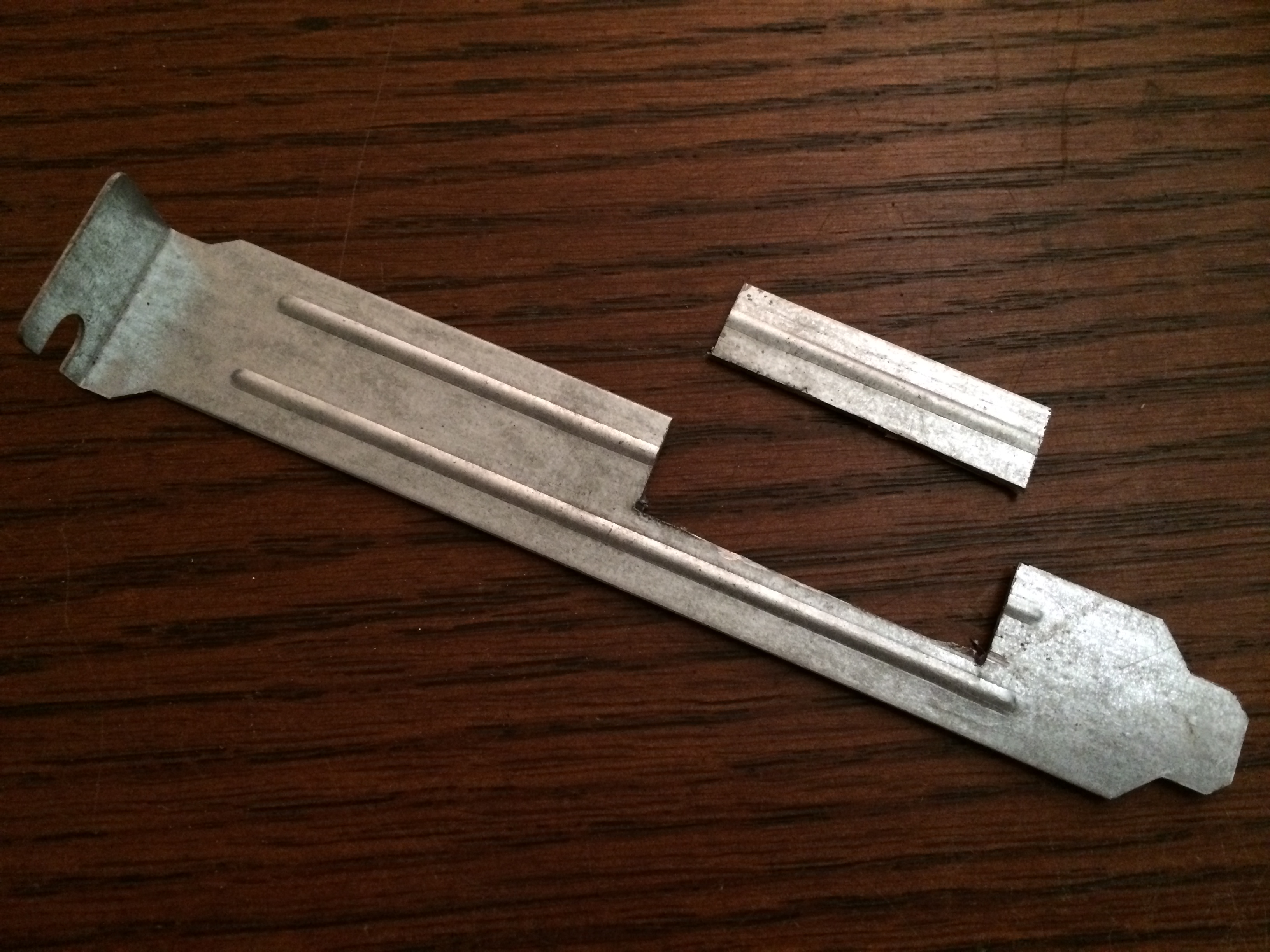

Using a bit of some old I/O riser card cover a small piece was cut out and with an added bonus of a structural bend in the middle that will help it retain rigidity over repeated usage. Next the lever needed a fulcrum on which to make its movement, in simple terms something was needed to act as a spacer. With some extra copper wire from an old power cord a small length was twisted and then soldered or tinned. This piece of wire will act as the fulcrum and can easily be trimmed later on.
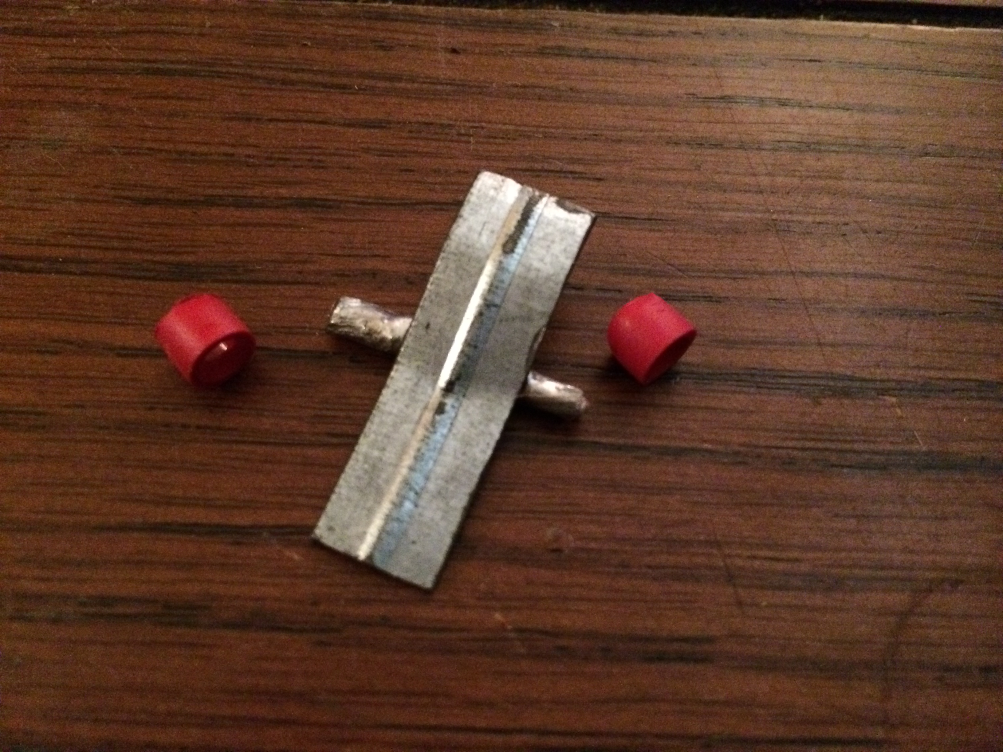
With the fulcrum attached to the lever again with more solder. As a general rule metals with steel in them can be soldered to generally with a bit of scuffing to ensure direct contact with the metal. The lever was given a few bends that will ensure pressure is placed on the correct area of the clip on the ethernet cable and provide the right amount of give in both directions. Lastly two small bits of a pen were cut as spacers and as supports and glued in place inside the I/O area with my super glue of choice.
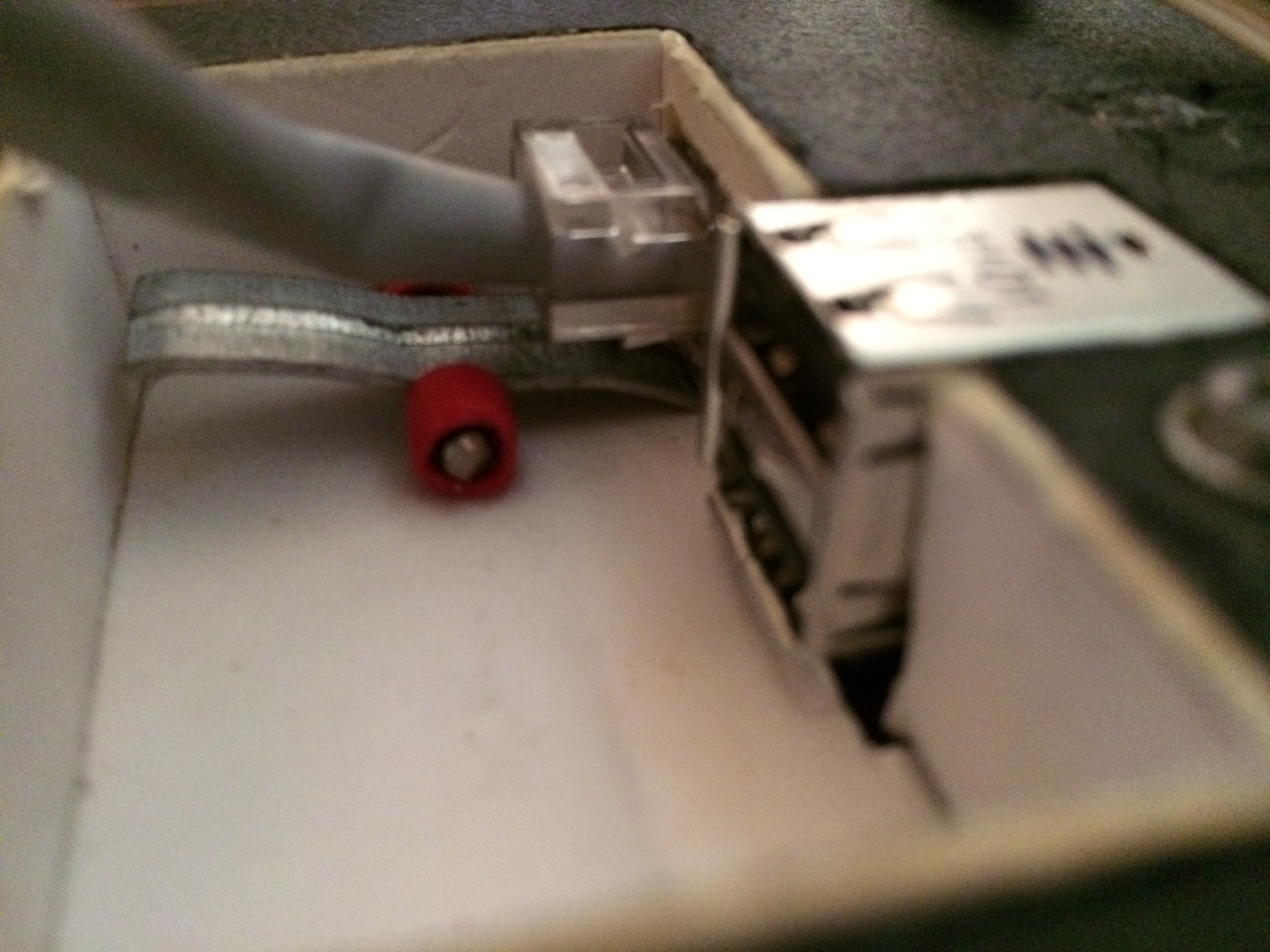

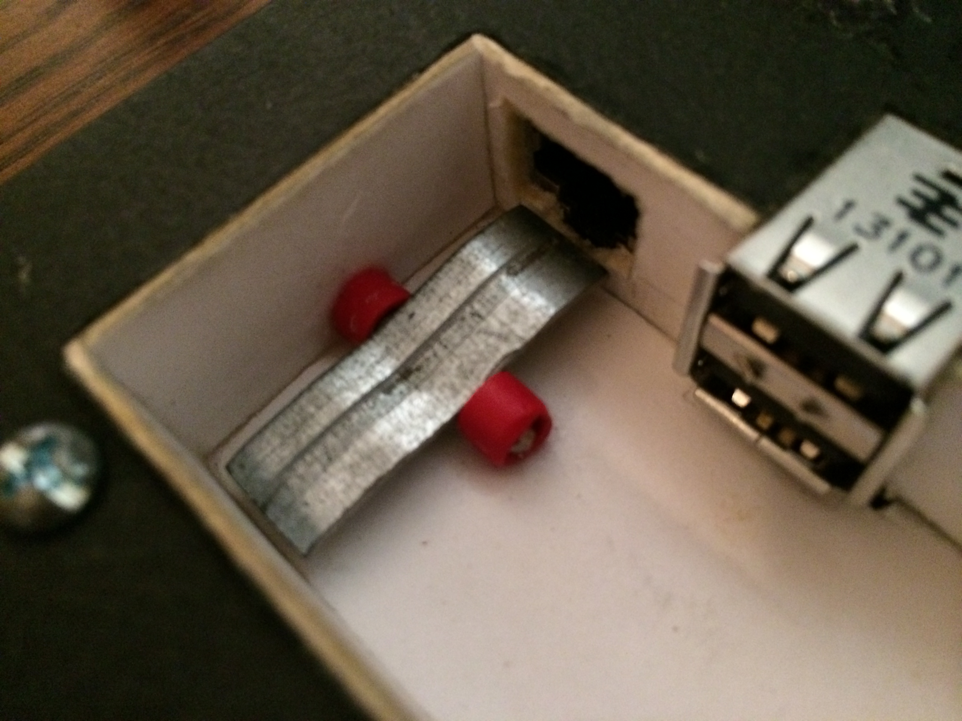
A moment of truth as an ethernet cable was connected, it might be hard to make out in the image but no pressure is placed on the clip of the ethernet cable’s connector until the lever is depressed. The lever fully pushes the clip of the cable flat against its connector providing an effortless removal of the cable. In all honesty it is as easy or perhaps easier to remove an ethernet cable now with a much larger lever that can be used to release the cable versus that tiny and somewhat fiddly clip.
The Button
Reddit’s The button… While nobody save its creator truly knows what happens when the clock strikes zero what we do know are the colors of flair a user receives when clicking at a certain time. You can only click once and only accounts created before April 1st can click.

Since the front-end of this project is really just a printed sheet it was easy to swap out the number template for one themed to match the various button flair colors. Since the defcon sign only has 5 sections I set the first section (blue) to represent times between 60 and 42 seconds.
Software
With the template cut and tested it was now time to connect the sign to websocket service powering The Button. Using examples from others in Python and Go it was easy to implement this in PHP and integrate it into the current structure of the sign’s software.
PHP has relatively poor support for websockets natively so using a simple library to help facilitate the connection was necessary. Enter Websocket PHP by Textalk available on Github Here.
$client = new Client('wss://wss.redditmedia.com/thebutton?h=...&e=...');
while (1) {
  $data = json_decode($client->receive(), true);
  echo $data['payload']['seconds_left'] . "\n";
}
Parts
- Raspberry Pi Model A or B depending on if you need ethernet or more RAM
- Hallmark Shadowbox Sentiments picture frame or other shadow box style picture frame
- 300 White Super Bright Diffused LEDs with Resistors
- 8GB class 10 SD Card but even a much lower class 4GB card would have worked fine
- 5x PNP Power Transistors
- Heavy 9000 weight poster board material
- Raspberry Pi Heatsinks