Description
Introduction
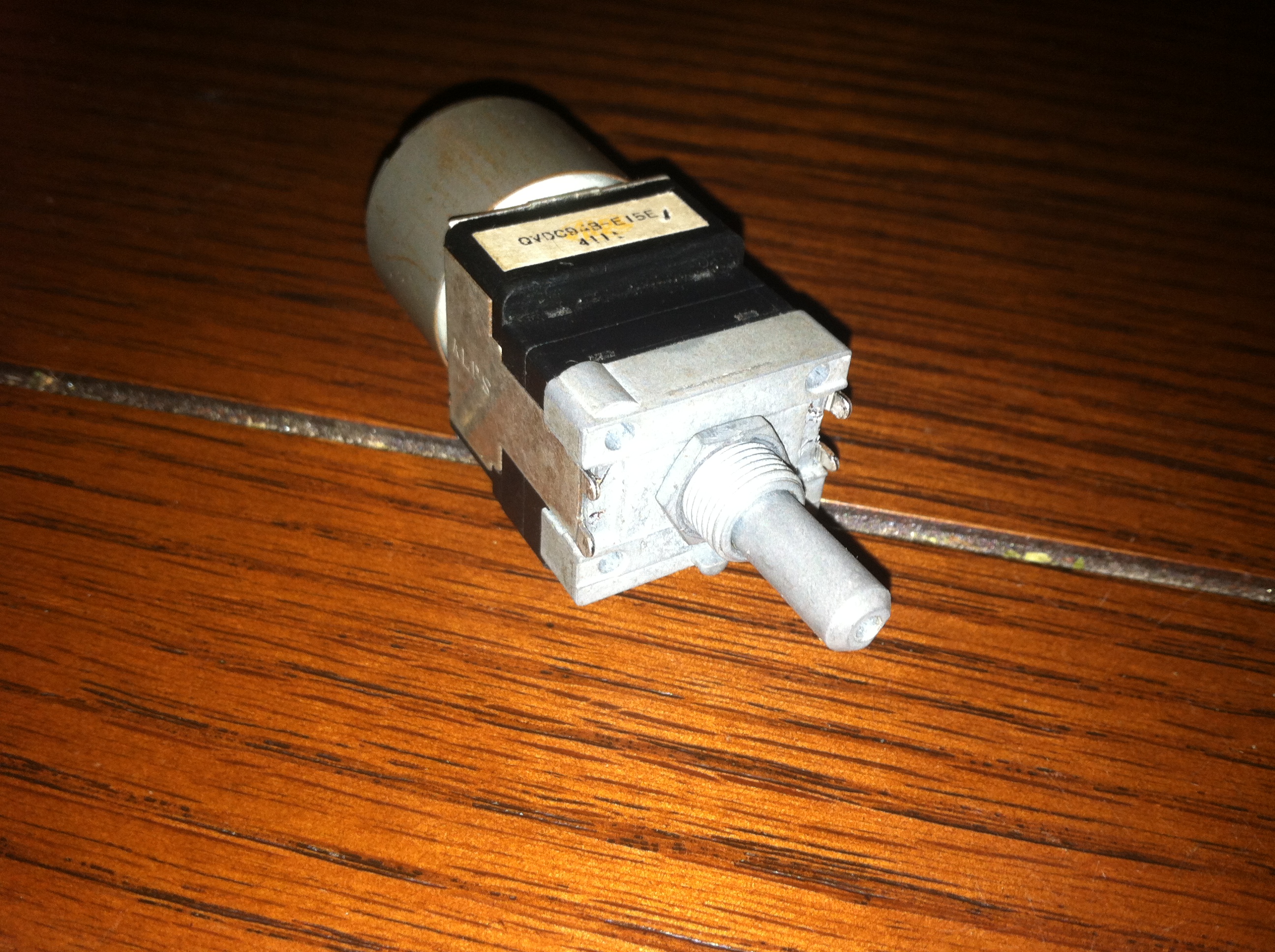
I’ve had this potentiometer in my parts bin for about 8 years or more with the hopes that one day it would find it’s way into one of my projects. While trying to use this for XodusAmp Redux I discovered that despite evidence to the contrary this was not a 4 channel potentiometer. I couldn’t find the pinout for this part so I decided to buy a new one for XodusAmp Redux that does have 4 channels. Not wanting to simply toss this one in the trash I decided to open it and find out what makes it tick.
Teardown

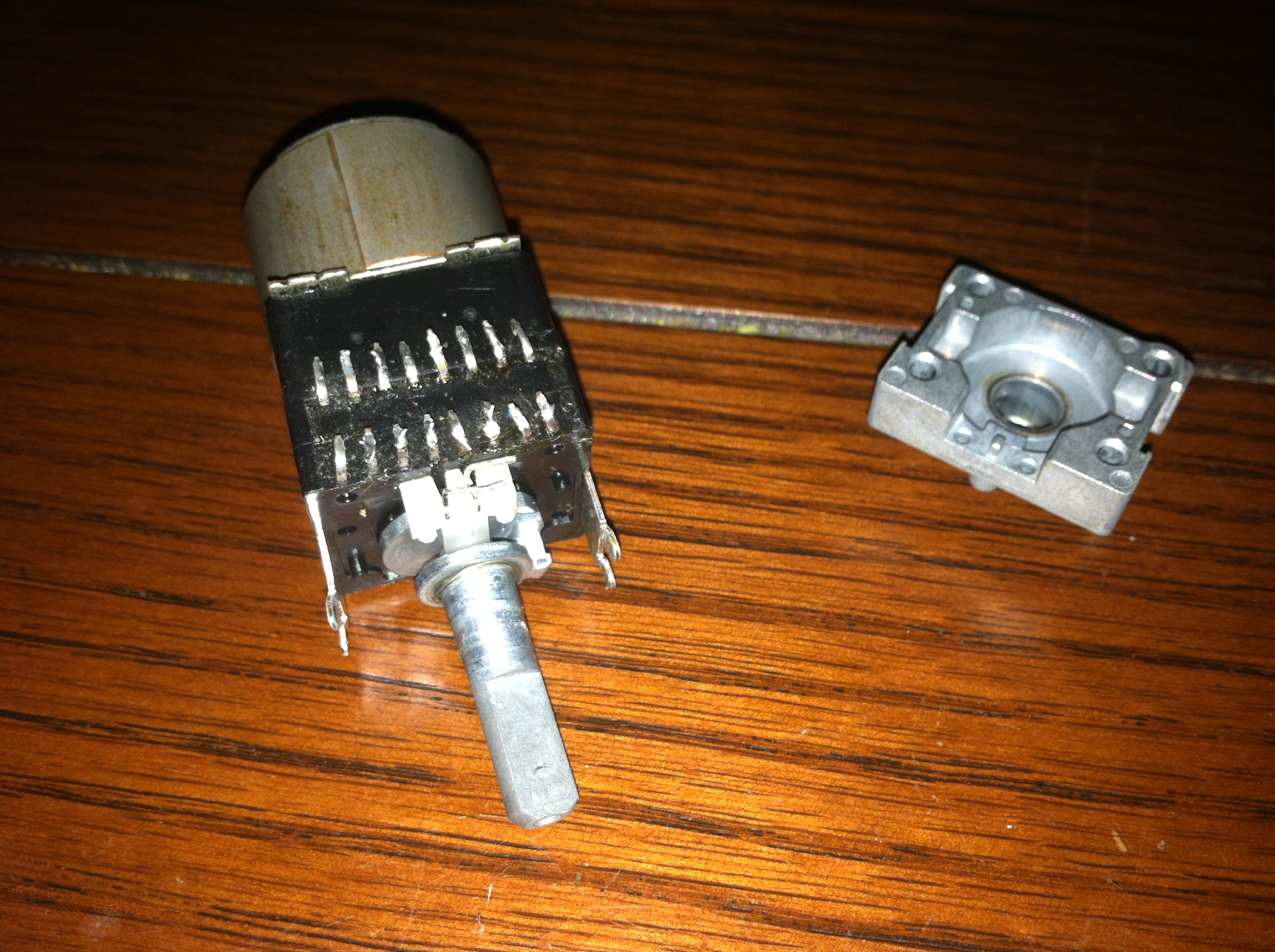
The potentiometer is easy to disassemble by bending the 4 tabs holding the front section forward.

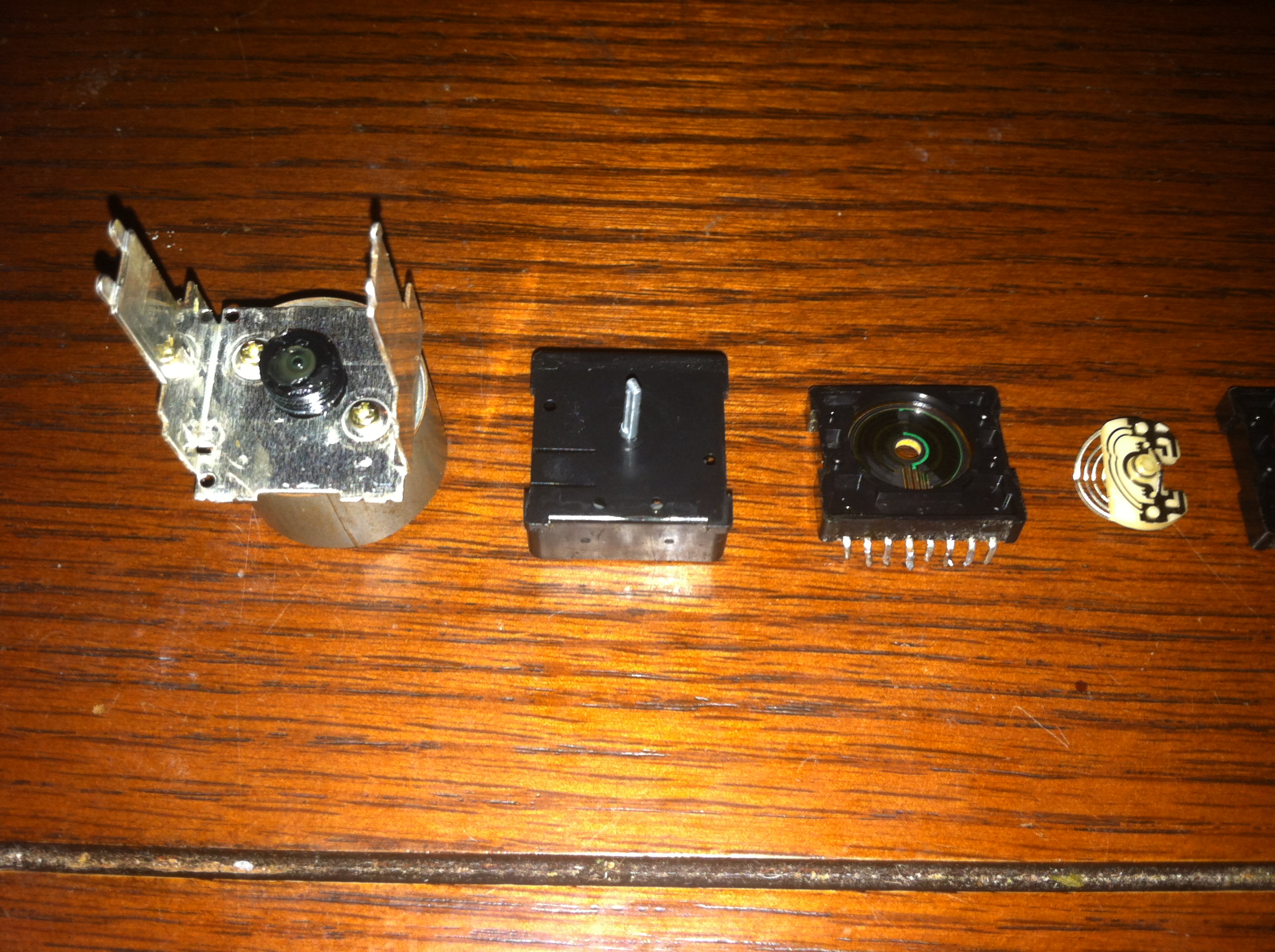
With the front removed the magic of how the knob can spin while being lit by a red LED.
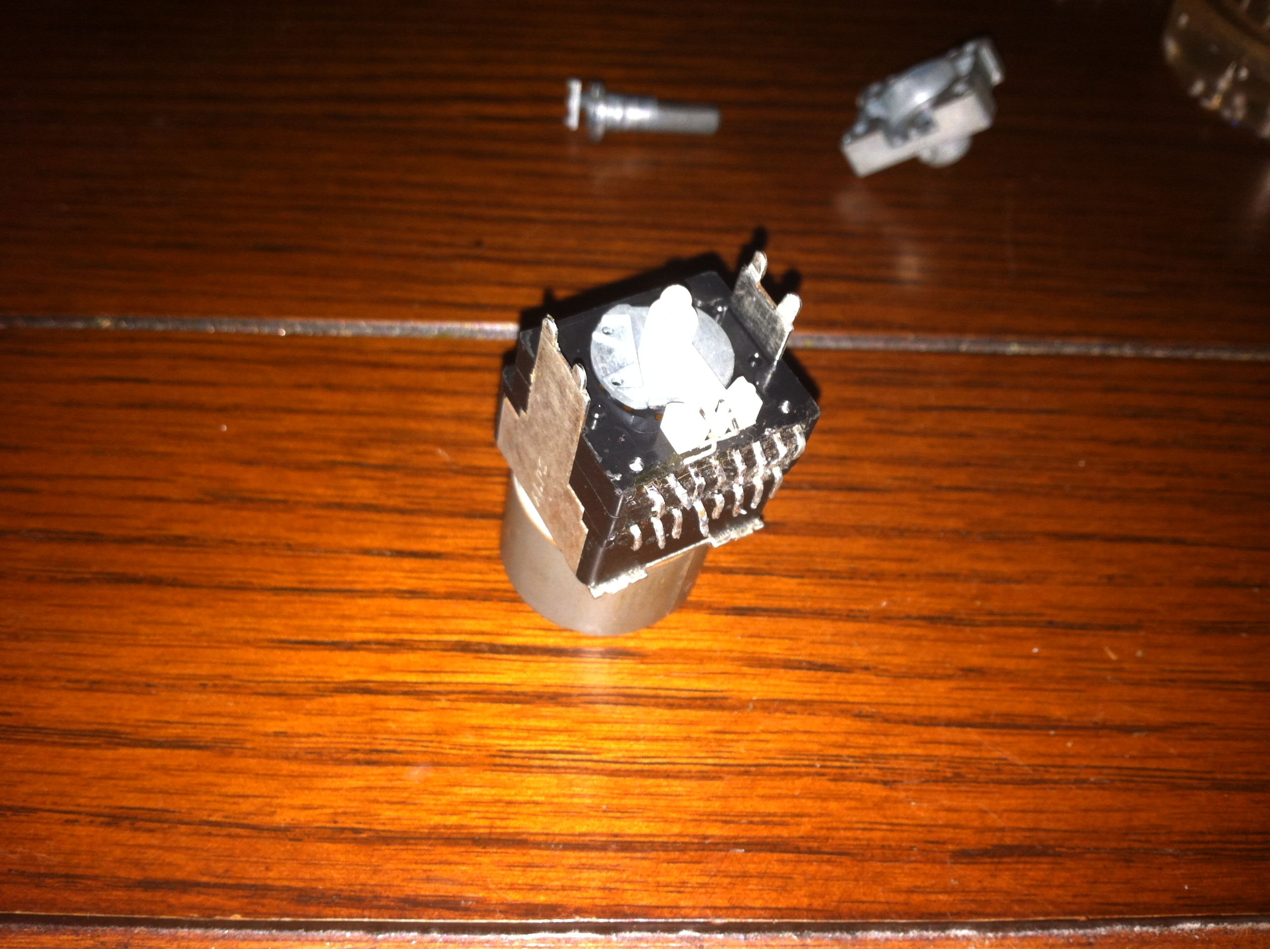
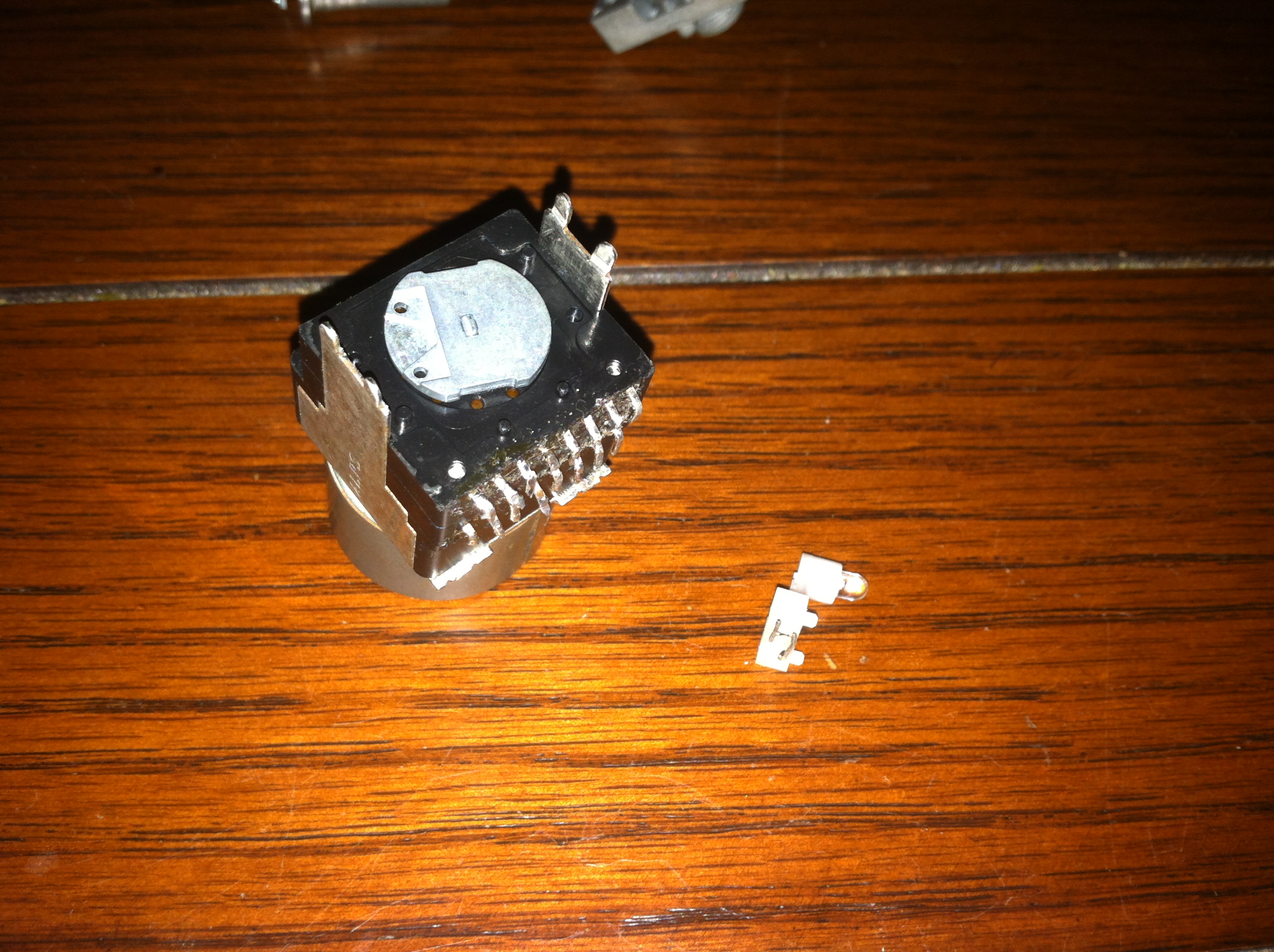
The knob fits into grooves on the rotor plate, there is a small gap between the knob and the rotor plate which allows the LED assembly to fit in between.
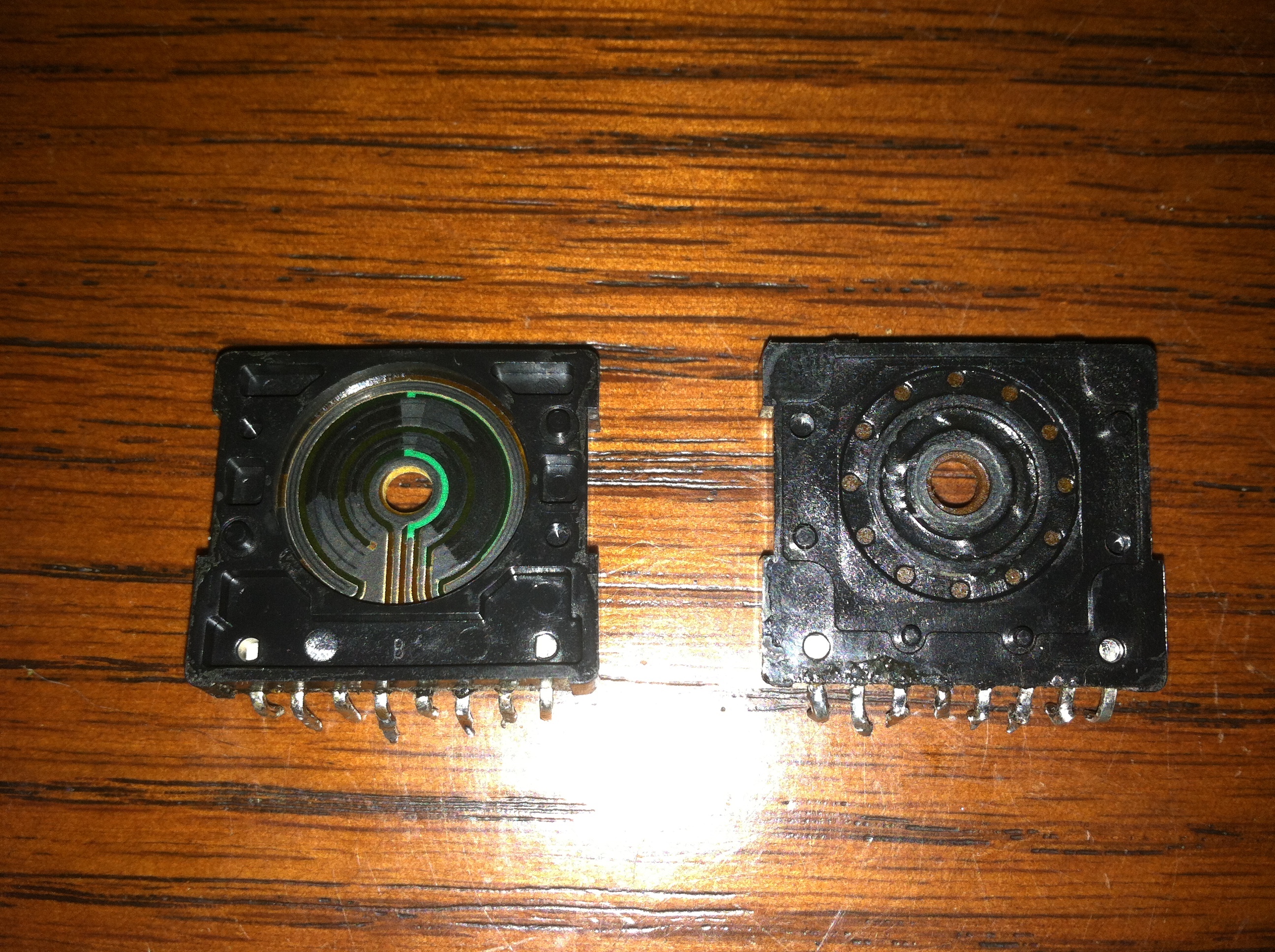
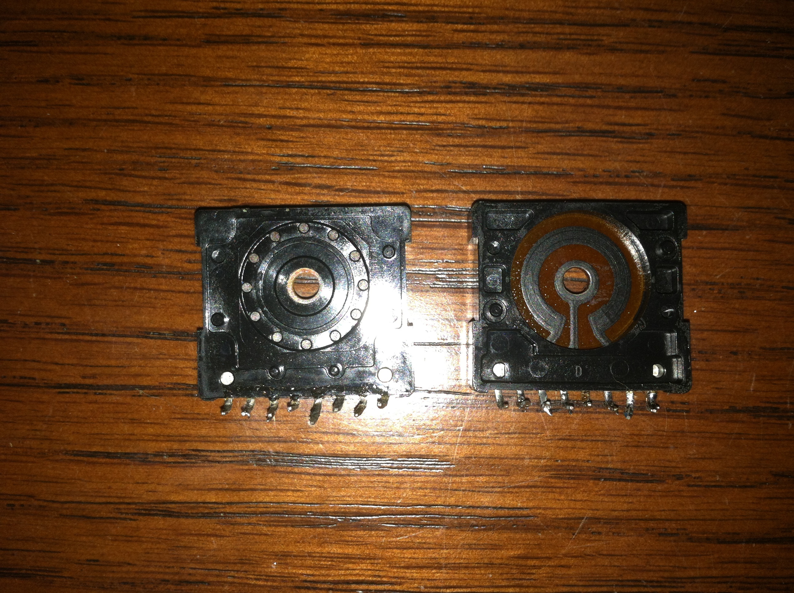
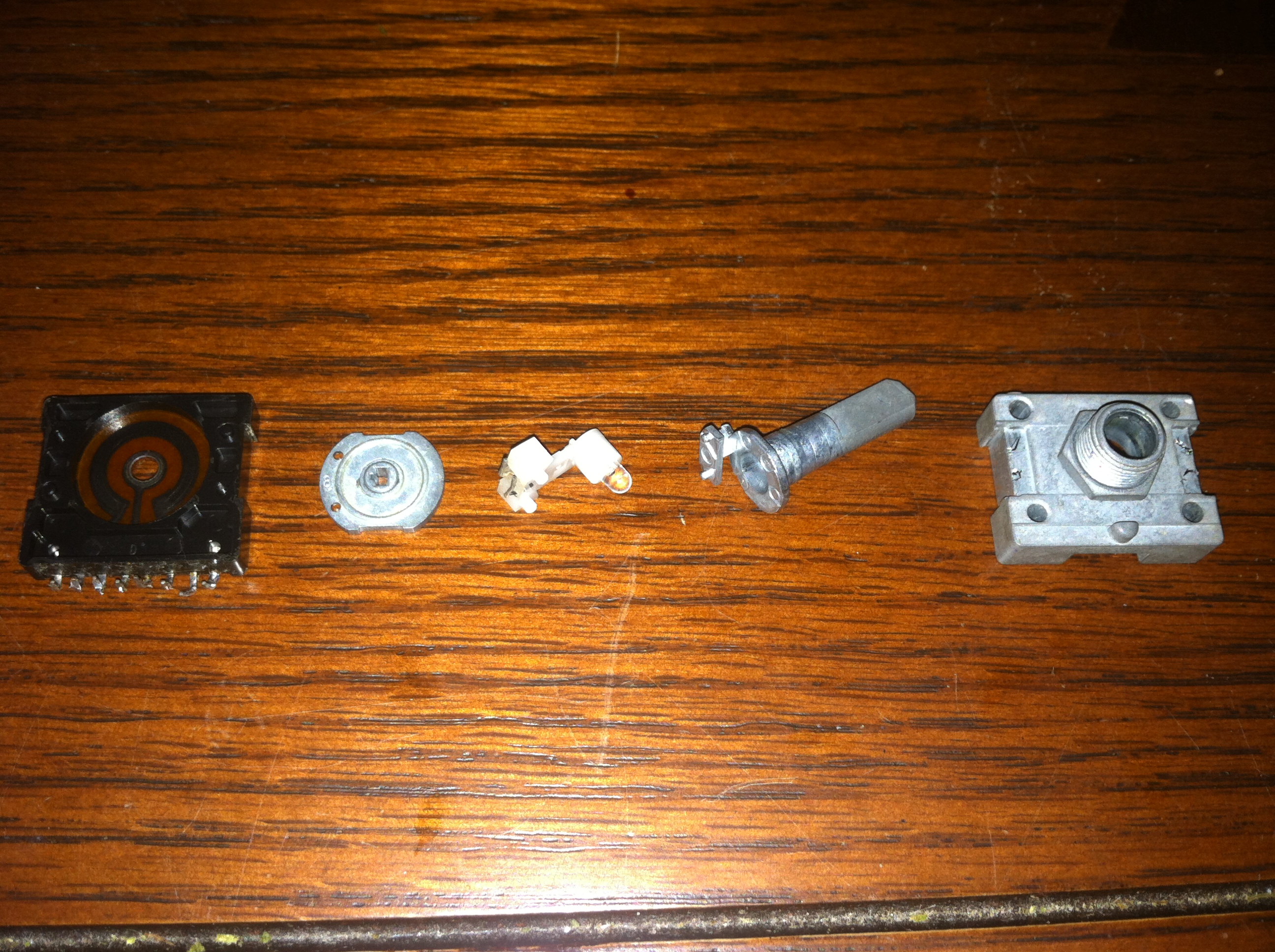
The meat of the potentiometer are the variable resistor pads shown above. It’s clear from looking at these that this was not a 4 channel potentiometer as I had previously assumed. From what I can tell there is one pad with only a single variable resistor and another with two resistors sharing a common pin. Most likely one of the pads was used for the volume and the other was used for some type of indicator of the volume level.
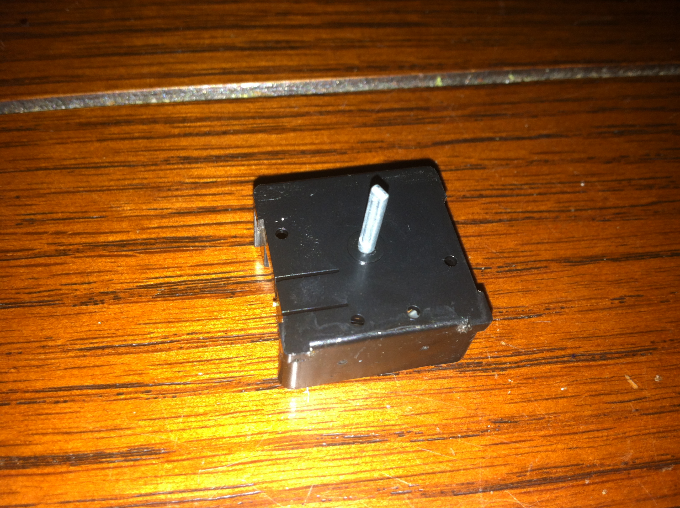
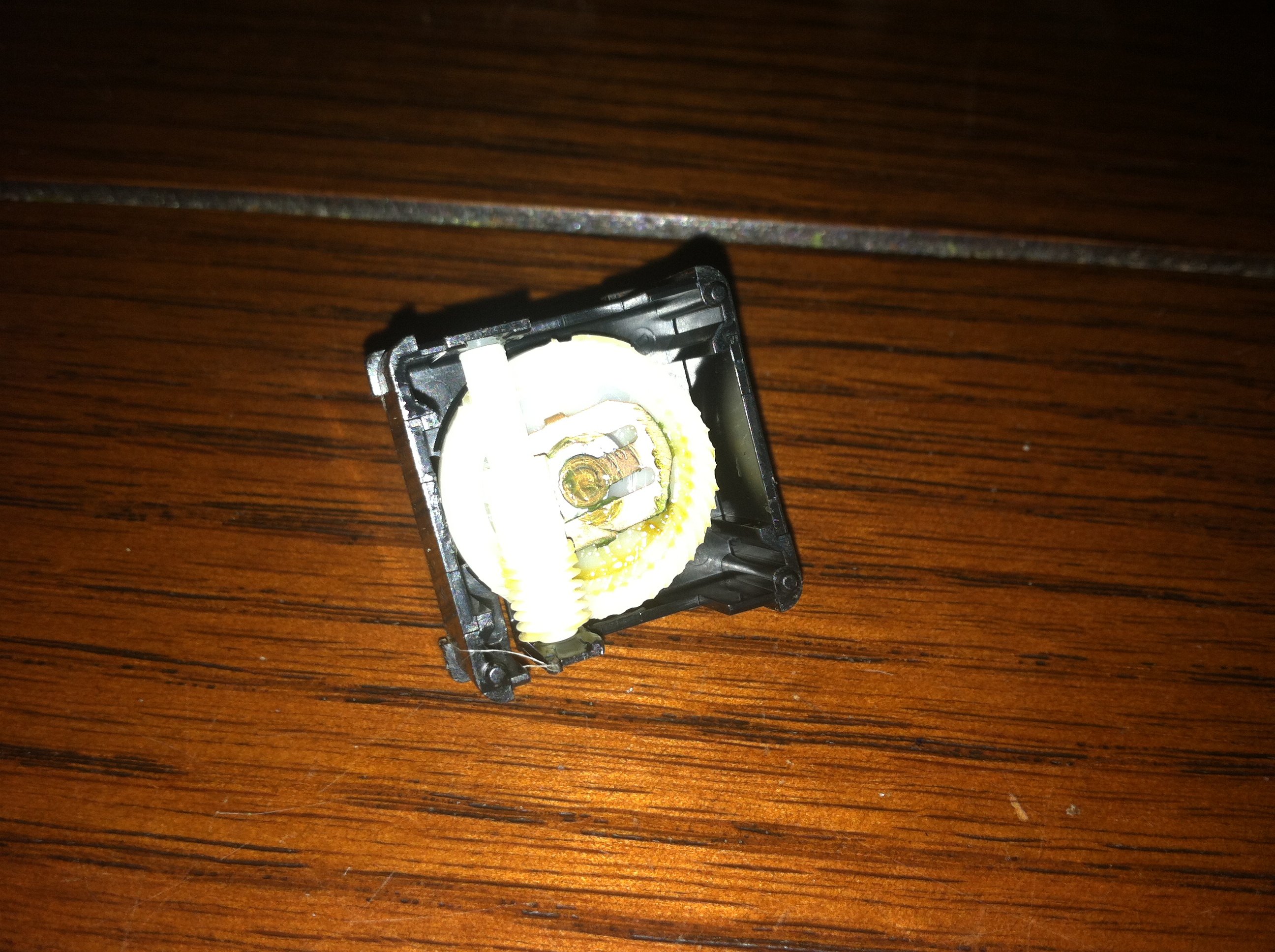
The last section is where the motor mates with the spindle that goes through the variable resistor plates and connects with the rotor in the front section. The motor drives the cylindrical gear which connects to the larger circular gear. The large circular gear connects to the shaft with a slip clutch allowing the potentiometer to be operated manually and ensuring the motor doesn’t burn up if it is told to keep spinning after the potentiometer has met its rotational limit.
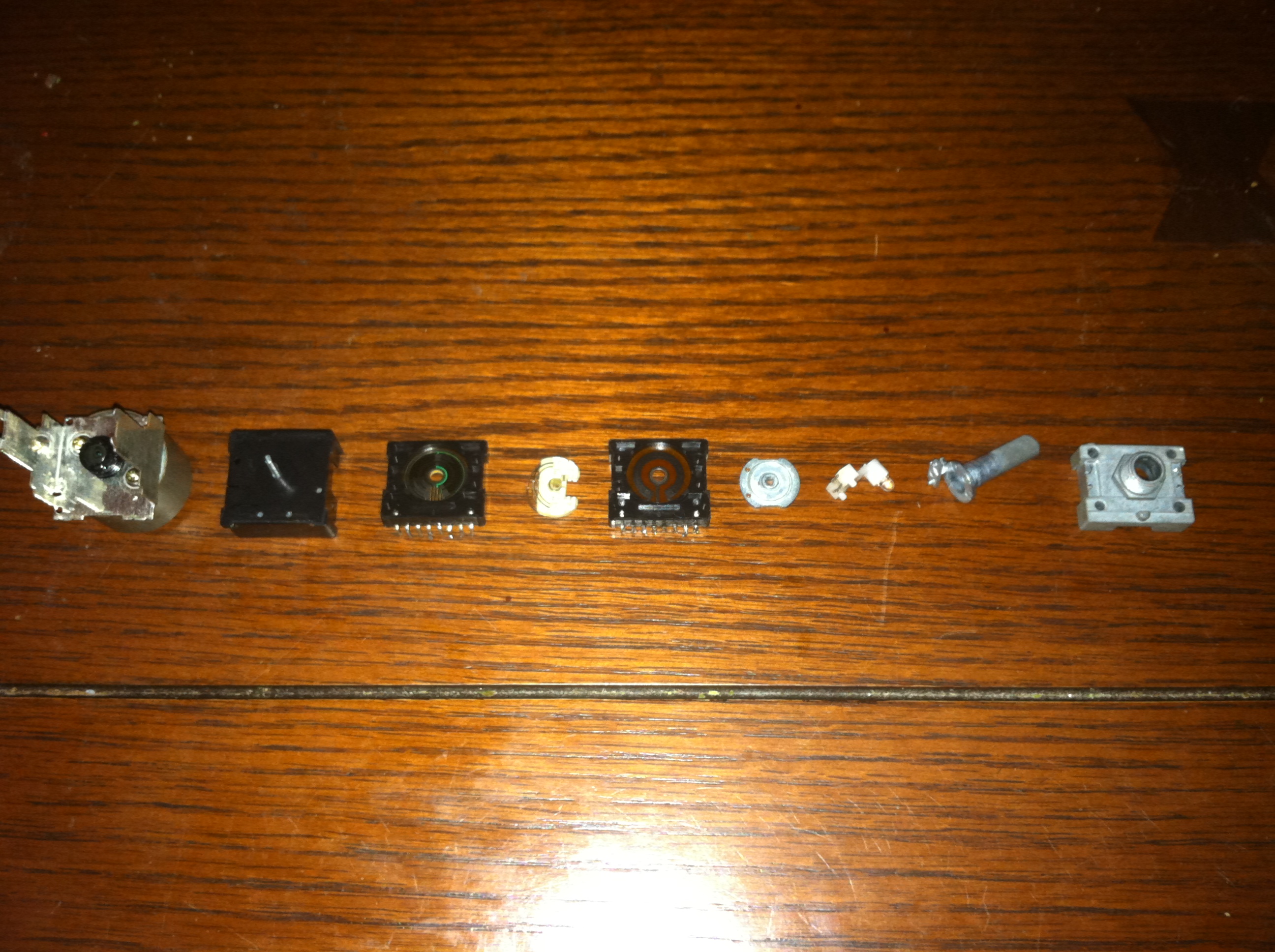
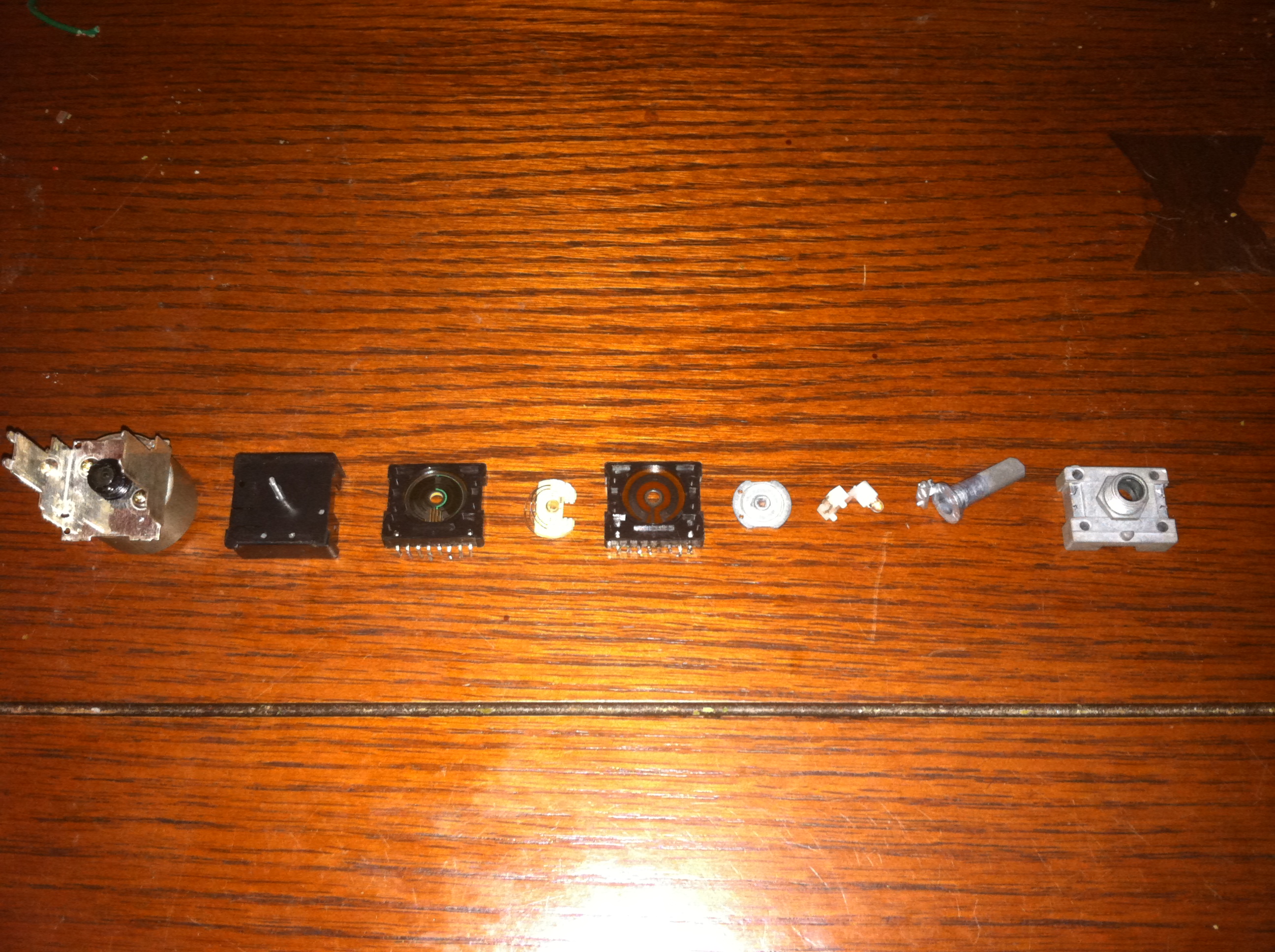
Here are a few pictures of all the parts in a straight line in order of how the potentiometer is assembled.
From left to right the parts are: Motor assembly and bracket, gear reduction assembly and shaft, first potentiometer pad, metal spring contacts, second potentiometer pad, rotor plate, LED assembly, knob assembly, and lastly the front plate.